N-1: our first rocket, with our own flight computer.
A 800 mm, 57 mm diameter model rocket with three through-the-wall plywood fins, flying on a certified 29 mm motor. An ESP32 flight computer in the nose section records every flight to its own memory and radios live data down to a ground station. Everything in plywood is cut on the Sculpfun S9 Pro from 3 mm sheet.
Design summary
Stability is how far the centre of pressure (CP, 558.0 mm from the nose) sits behind the centre of gravity (CG, 451.7 mm with a motor), measured in body diameters.
Between 1 and 2 means it flies straight. These figures use estimated masses. Weigh the real parts, update design.py, and confirm in OpenRocket with your actual motor before the first flight.
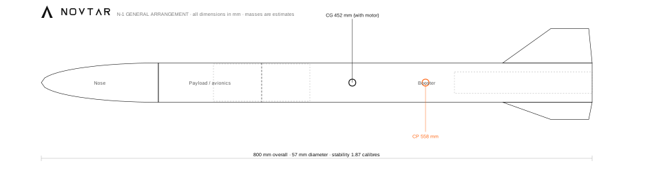
How N-1 is put together
| Section | Length | What is inside |
|---|---|---|
| Nose cone | 170 mm + 40 mm shoulder | Laser-cut: 68 numbered 3 mm plywood rings stacked on an 8 mm dowel, glued, sanded to the ogive curve, filled, primed and painted. The shoulder rings are hollow so the sled's top tab fits inside. Held in the payload tube by two small screws so it comes off for access. |
| Payload tube | 150 mm | The avionics bay: the sled with the flight computer, sensors, battery and switch. Three 2.5 mm vents let the barometer feel outside air pressure. |
| Coupler | 140 mm | Half glued into the payload tube, half slides into the booster. Sealed at the bottom by a 9 mm plywood bulkhead with an M5 eye bolt. |
| Booster tube | 480 mm | Parachute, flame-proof blanket and shock cord in the top; motor mount and fins at the bottom. |
| Motor mount | 200 mm, 29 mm motor | Three rings: aft ring flush with the end (with two Kaplow-style clips), fin ring at 126 mm, top ring at 197 mm from the aft end. |
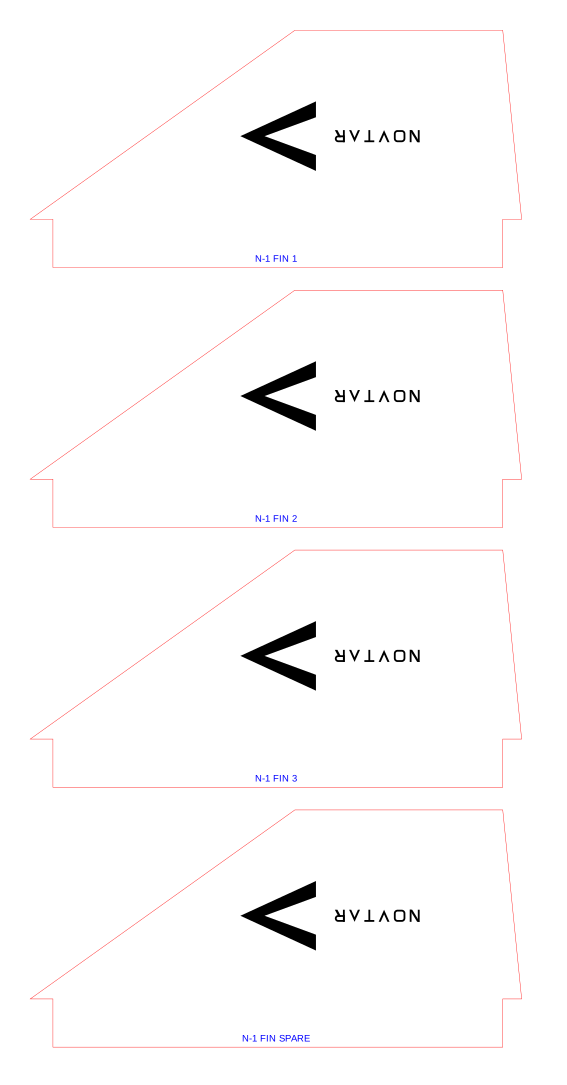
| Fins | 3 × root 130, tip 55, span 50, sweep 70 mm | 3 mm plywood through-the-wall fins, epoxied to the motor tube and filleted outside. |
What to buy
Rocket structure (UK rocketry suppliers)
| Item | Spec | Notes |
|---|---|---|
| Body tube | about 54 mm inside, 57 mm outside, 1 m | Cut into 480 mm booster and 150 mm payload. Measure it and update design.py. |
| Coupler tube | fits inside the body tube, 140 mm | Should slide in snugly without forcing. |
| Motor mount tube | 29 mm, 200 mm long | |
| Dowel | 8 mm hardwood dowel, about 210 mm | Lines up the nose cone rings while the glue sets. The rings themselves are on the laser sheets. |
| 3 mm birch plywood | 6 boards, laser grade, at least 400 × 400 mm | 5 boards for the parts, 1 spare for tests and mistakes. With smaller boards the nose cone sheets need splitting first. |
| Parachute | 67 cm nylon, with swivel | Gives about 5.5 m/s descent. |
| Recovery | 1.5 m Kevlar cord, 2 m elastic shock cord, 2 quick links, flame-proof blanket | Kevlar where it meets the motor heat; elastic for the rest. |
| Hardware | M5 eye bolt with nuts and washers, 2 × M3 T-nuts and M3 × 10 bolts, 2 small screws for the nose | |
| Launch guide | Two 1010 rail buttons (our choice, to fit the base kit's 1010 rail), and two backing pads from sheet 02 | If your club only has rods, ask before you fit them. |
| Glue and finish | wood glue, 30-minute epoxy, filler, primer, matte black and white paint, clear satin varnish | Epoxy for the motor mount and fins. Matte white paint over filler and primer on the nose, matte black paint over primer on the tubes, clear satin varnish on bare birch, engraved mark showing on the fins. |
| Wordmark decal | NOVTAR wordmark, white vinyl decal, 22 mm tall, about 154 mm long | Printed by any sign or sticker shop from brand/wordmark-white.svg. Goes on the booster, centred 470 mm from the nose tip, reading from the tail towards the nose (bottom to top when it stands), the same way the engraved mark on the fins points. |
Flight computer (AliExpress)
| Item | Qty | Notes |
|---|---|---|
| Heltec WiFi LoRa 32 V3, 868 MHz version, with antenna | 2 | One in the rocket, one as the ground station. |
| GY-BMP280 barometer (3.3 V) | 1 (+1 spare) | Altitude from air pressure. |
| GY-521 MPU6050 accelerometer and gyro | 1 (+1 spare) | Up to 16 g and 2000°/s. |
| 1S LiPo, 400 to 600 mAh, with the board's battery plug | 2 | Check the plug polarity matches the board before connecting. |
| 3 V active buzzer, small slide switch | 2 each | Buzzer helps find the rocket after landing. |
| Silicone wire, heat shrink, M2.5 nylon standoffs, 2.5 mm zip ties | No PCB needed: wire the modules directly. | |
| Status LEDs: 3 LEDs cut from your 3-pin RGB strip, one 330 Ω resistor | 1 | Must be a 5 V addressable strip (WS2812B type: 5V, GND, DIN). A 12 V strip will not light from the rocket's battery. Clear epoxy or hot glue fills the 5 mm windows. |
Motor
A certified 29 mm single-use motor with an average thrust of at least 28.5 N (F or small G class). Choose the exact motor and its ejection delay in OpenRocket so the parachute comes out near the top. Motors are bought from UK rocketry suppliers and age limits can apply, so an adult or your club mentor handles buying and preparing them.
Cut list for the S9 Pro
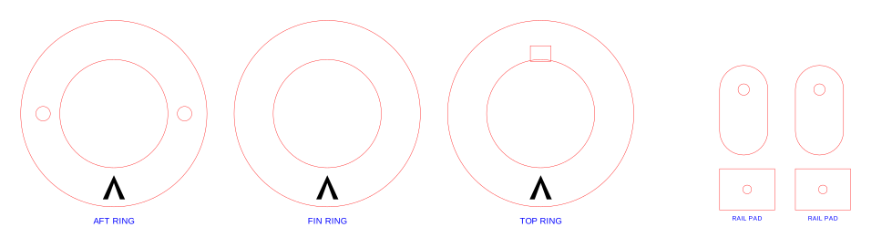
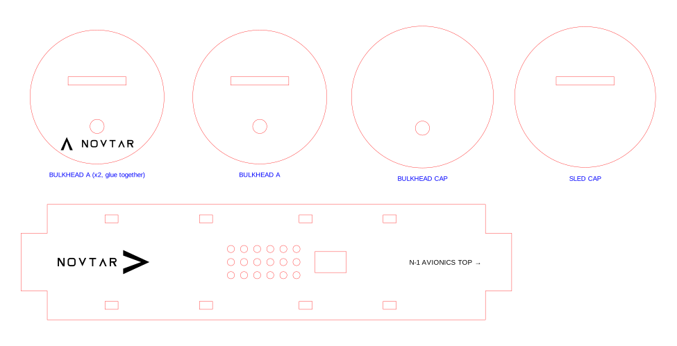
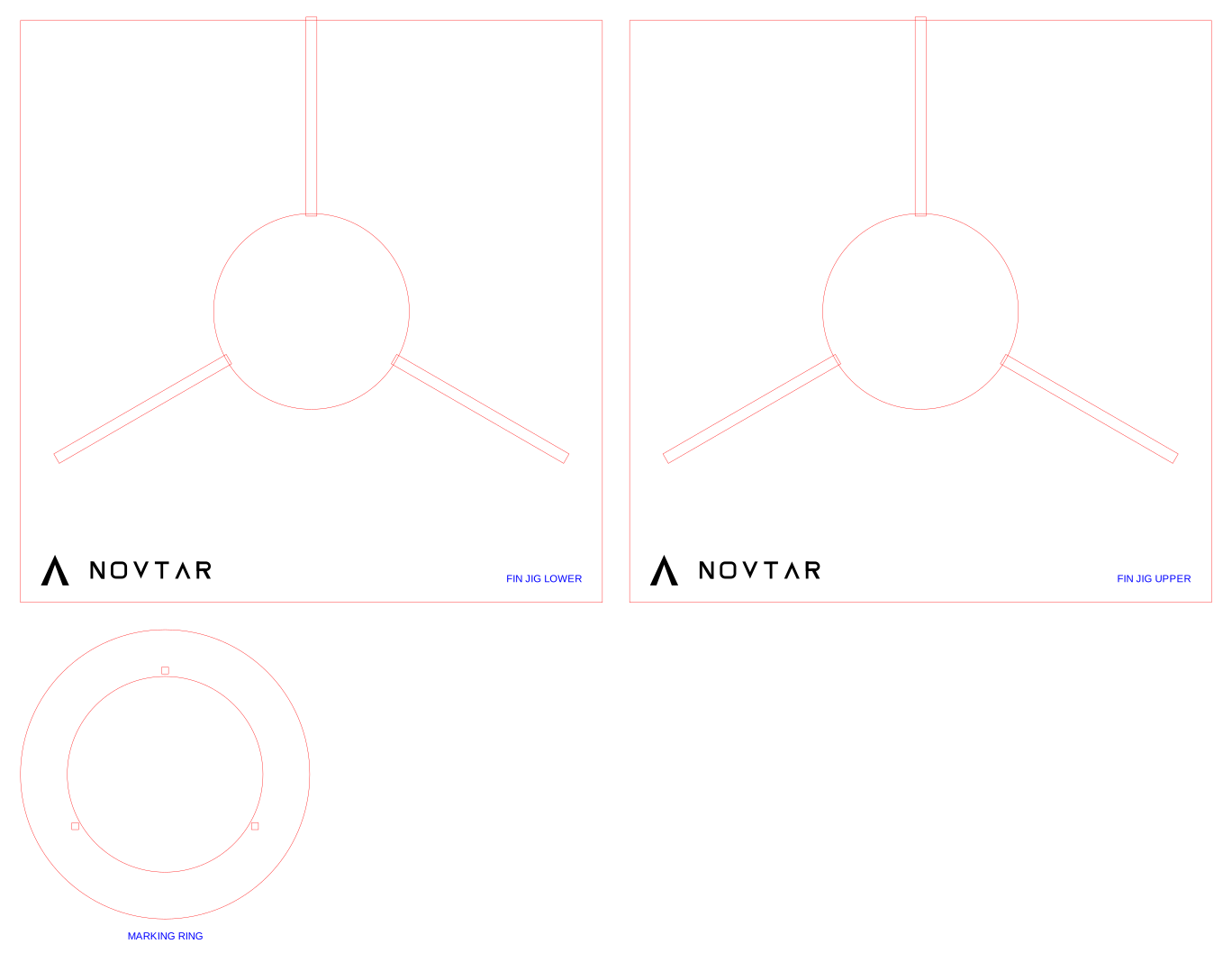
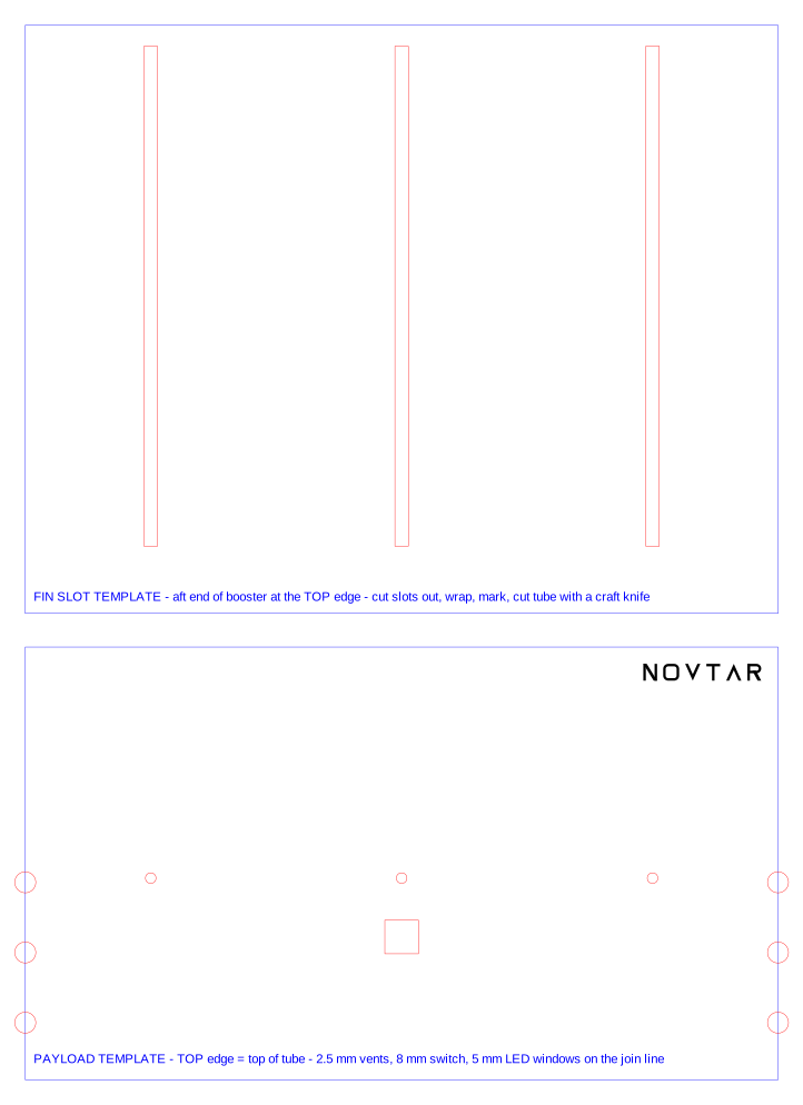
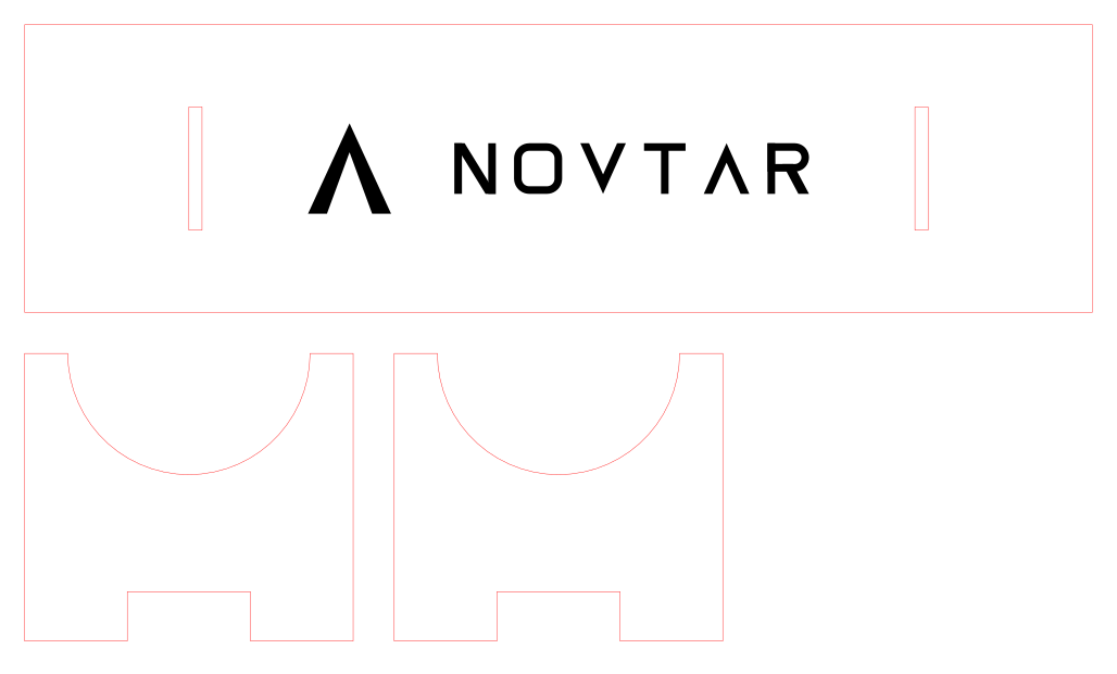
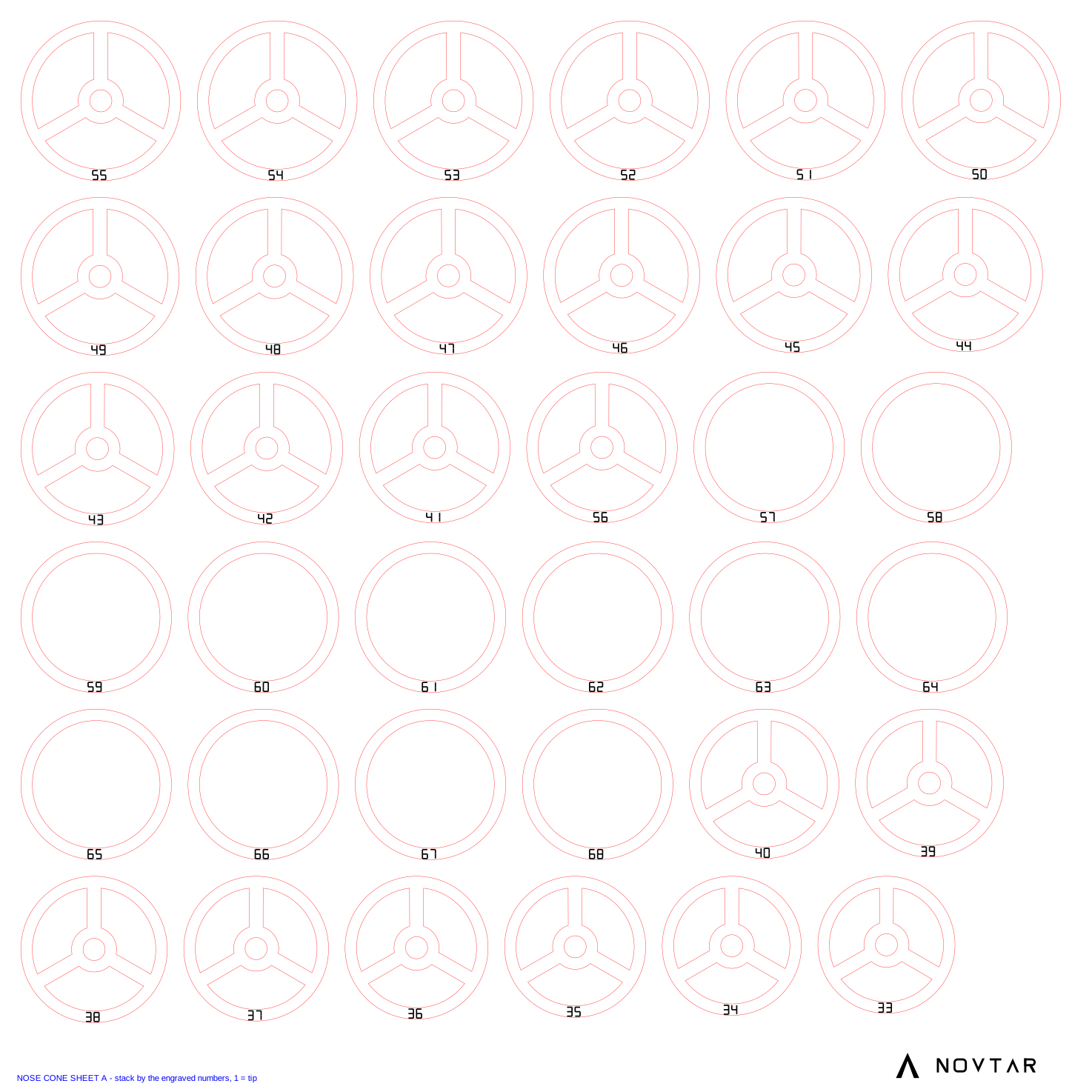
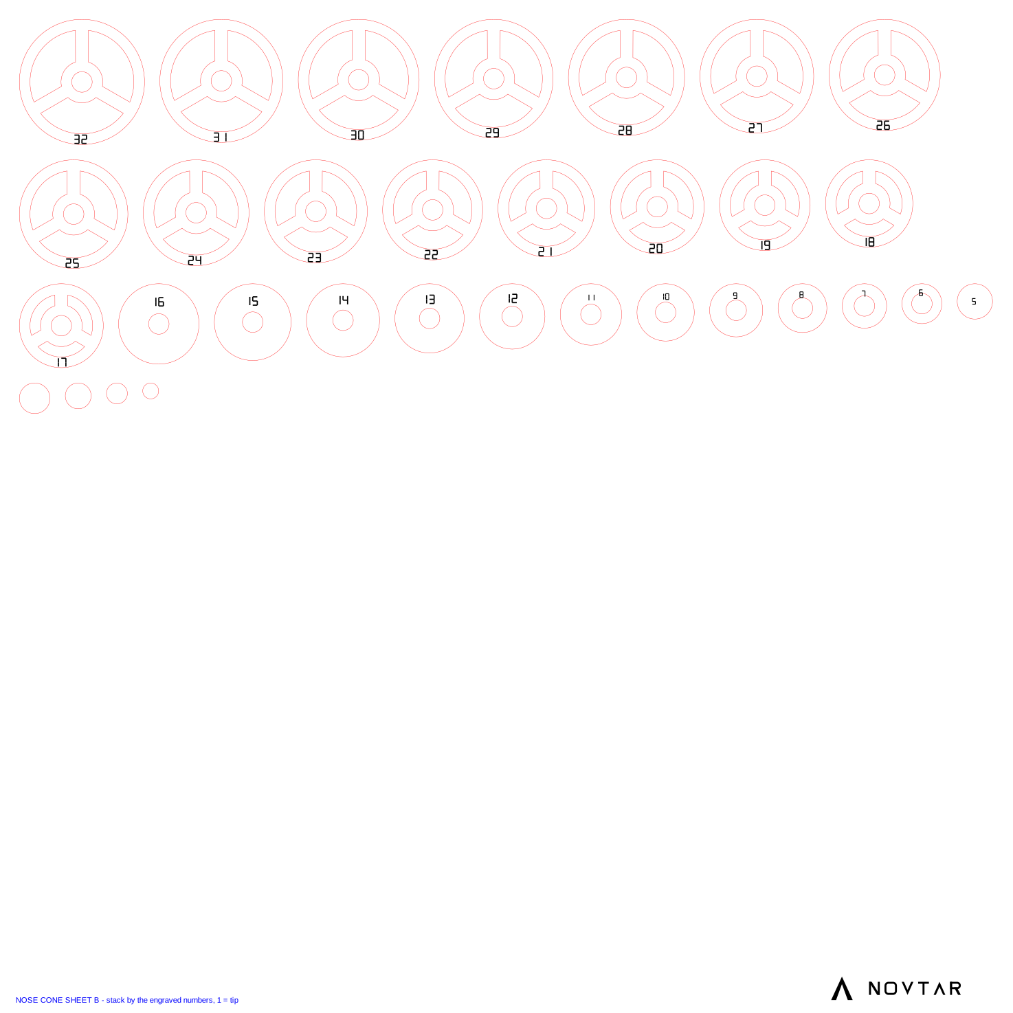
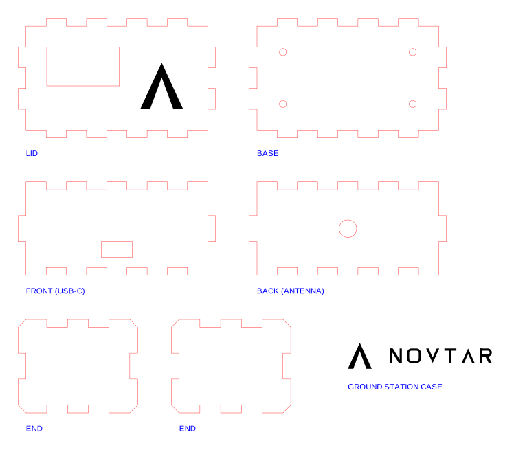
Before the first cut: set up safely
- Wear the laser safety glasses made for your laser's wavelength, and keep the shield in place. Anyone else in the room needs them too.
- Vent the smoke outside (window fan or the extractor duct). Plywood smoke is irritating and the glue in it is not good to breathe.
- Keep a fire extinguisher or fire blanket within reach. Never leave the laser running unattended, even for a minute.
- Run air assist if you have it: cleaner cuts and fewer flare-ups.
- Only cut plywood, paper and card. Never PVC or vinyl: they release chlorine gas.
- An adult should be around for the first sessions.
Tests, in this order
- Focus. Set the focus height with Sculpfun's focus gauge on the actual plywood. Every test after this depends on it.
- Material test. Run
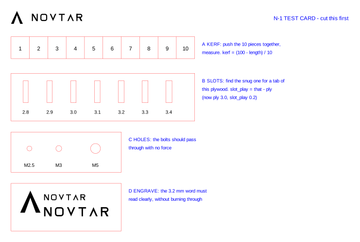
out/lasergrbl/00_material_test.ncin LaserGRBL on a scrap of the same plywood (about 145 × 75 mm). Engrave squares go from 20 to 60% power and 1000 to 4000 mm/min. Cut squares are at full power, from 150 to 500 mm/min, with 1 to 4 passes, each with a 3 mm hole. Pick the cleanest engrave, and the cut square that drops out on its own with a clean hole and the least charring. Put both inLASERintools/lasergrbl.pyand run it again. - Test card (
00_test_card.svg), cut with those settings:- A, kerf: push the ten pieces together and measure with the calipers. kerf = (100 − length) ÷ 10. Put it in
kerfindesign.py. - B, slots: measure the plywood's real thickness first and put it in
ply. Find the slot where a scrap of the plywood fits snugly.slot_play= that slot −ply. - C, holes: M2.5, M3 and M5 bolts should pass through with no force.
- D, engraving: the small 3.2 mm word, the size used on the fins, must read clearly without burning through.
- A, kerf: push the ten pieces together and measure with the calipers. kerf = (100 − length) ÷ 10. Put it in
- Run
python design.pyafter changing any number. Every file is regenerated with the new sizes. - Fit ring (
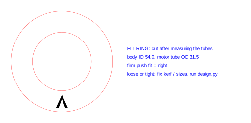
00_fit_ring.svg), once the tubes have arrived and their sizes are indesign.py. It must slide onto the motor tube and into the body tube with a firm push. Only then cut the real parts.
Cutting order
We use LaserGRBL (free). It has no colour layers, so tools/lasergrbl.py turns each SVG into a ready G-code file in out/lasergrbl/: engrave the logos first, then cut. Open the .nc file and press play, with the sheet's front-left corner at the laser's 0,0. A diode laser cuts cleanest with several faster passes rather than one slow one. The files cut the whole sheet one pass at a time so each line cools, smallest shapes first so holes are done before parts drop free, and every closed cut runs 0.8 mm past its start so it always closes. Air assist helps a lot if you have it. Keep the plywood flat (weigh the corners down) so the focus stays the same across the sheet. The SVGs still work in LightBurn: red = cut, black = engrave, blue = notes (output off).
- Board 1:
04_jigs,02_motor_mount_ringsand the fit ring. Build the motor mount first, so these come first. - Board 2:
01_finsand06_stand. - Board 3:
03_avionics_bay,08_ground_station_caseand the test card. - Boards 4 and 5:
07_nose_cone_Aand07_nose_cone_B. These are the longest jobs. Check the ring numbers as you lift them out. 05_wrap_templatesis printed on paper at 100% scale, not lasered.
Step by step
- Measure and generate. Calipers on every tube. Put the real numbers in
design.py, runpython design.pythenpython tools/build_book.py. Check the stability is still 1 to 2. - Cut the tubes. Booster 480 mm, payload 150 mm, coupler 140 mm, motor tube 200 mm. Wrap paper round the tube as a straight guide and cut with a fine saw or sharp knife.
- Fin slots. Tape the fin slot template round the booster with its top edge on the aft end. Mark through the slots, use the marking ring to check the lines are 120° apart, and cut the three slots with a sharp knife. Test with a fin.
- Motor mount. Press the two M3 T-nuts into the aft ring from the front. Mark the motor tube from the aft end: fin ring at 126 mm, top ring at 197 mm. Epoxy the fin ring and top ring on. Tie the Kevlar cord round the motor tube between them and lead it through the top ring's notch.
- Fit the motor mount. Spread epoxy inside the booster where the two rings will sit and slide the motor mount in until the aft end of the motor tube is flush with the booster. The aft ring goes on last.
- Fins. Slide both fin jig plates over the booster. Put epoxy on each fin tab and root, push the fins through the slots onto the motor tube, and line them up in the jig slots. Check each fin is square to the tube and leave it to cure fully.
- Inside fillets and aft ring. Through the aft end, run a fillet of epoxy where each tab meets the motor tube. Then glue the aft ring in flush. Add outside fillets along each fin root.
- Rail buttons. In line in the gap between fins 2 and 3 (opposite the wordmark): one 25 mm above the aft end, one at the balance point with a motor in (about 348 mm above the aft end, estimate). Glue a backing pad inside the tube under each before the payload goes on, drill through and screw the buttons in.
- Avionics bay. Glue the coupler 70 mm into the payload tube. Laminate two bulkhead A discs and the cap with wood glue, fit the eye bolt, and epoxy the stack into the bottom of the coupler with the cap against its end. Wrap the payload template round the payload tube (top edge at the top) and drill the vents and switch hole, then the 3 5 mm LED windows on the template's join line (opposite the switch; the lower one goes through the coupler too). Fill the windows with clear epoxy or hot glue and sand flush, so they pass light and keep the bay sealed.
- Nose. Push the nose shoulder into the payload tube and drill two small holes opposite each other through the tube into the shoulder. Two screws hold it, and come out for access.
- Recovery. Kevlar from the motor mount to a quick link, elastic shock cord to the avionics bay eye bolt, and the parachute clipped on about a third of the way from the nose end. Wrap the parachute in the flame-proof blanket.
- Finish. Fill the tube spirals, prime, then paint: matte black body, white nose. Apply the NOVTAR wordmark decal on the booster, reading from the tail towards the nose. Never laser-cut vinyl yourself: it gives off chlorine. A sign shop cuts it.
- Weigh and re-check. Weigh every section, update the masses in
design.py, rerun it, and model the finished rocket in OpenRocket with your chosen motor.
Wiring and firmware
- Both sensors share one I²C bus with the board's screen: SDA GPIO17, SCL GPIO18, power from 3V3. BMP280: CSB to 3V3 and SDO to GND (address 0x76). MPU6050: AD0 to GND (address 0x68).
- Buzzer + to GPIO47, - to GND. Battery to the board's battery socket through the slide switch.
- Status LEDs (added 18 Nov 2026): DIN to GPIO4 through a 330 Ω resistor, GND to GND, + to the battery side of the slide switch (after the switch, so they go off with it). A 1S LiPo gives 3.7 to 4.2 V; WS2812B-type LEDs are made for 5 V and normally run on this, but check yours on the bench. We assume your strip is WS2812B type: if its LEDs or label say 12 V, it is not for the rocket.
- Always fit the antenna before powering on. Transmitting without one can damage the radio.
- Pins are taken from Heltec's V3 pinout. Check them against the diagram for your exact board before soldering.
The sled (167 mm)
Heltec board on M2.5 standoffs in the hole field, sensors and battery held with zip ties through the slots, and wires through the pass-through. The status LED strip sticks on the back face (the side without the Heltec), on the centre line, with its first LED 56 mm below the top of the payload tube, so the LEDs line up with the windows. The bottom tab goes into the bulkhead slot, and the sled cap drops over the top tab. The nose shoulder holds it all down.
Status LEDs: what they mean
Three LEDs, seen through the windows. They only show what the computer already knows; they never switch, fire or release anything. Brightness is capped, so the three together add roughly 12 mA (an estimate from the usual WS2812B figures; measure yours).
| What you see | Meaning |
|---|---|
| All blue | Starting up and measuring the ground level. Keep it still. |
| LED 1 green (blinking) / red | Barometer and motion sensor both found / one is missing: do not fly. |
| LED 2 green / amber / red | Logging to flash / flash nearly full (download, then rm) / not logging: do not fly. |
| LED 3 green / amber / red | Radio fine and battery at or above 3.7 V / no battery reading / radio failed or battery below 3.7 V: do not fly. |
| Dark | In flight (saves power), or switched off. |
| White flash every 2 s | Landed. Go and find it. |
| Fast white flashing for 10 s | LOCATE sent from Mission Control. |
Mission Control's GO / NO-GO is still the one that counts. The LEDs are so you can see the same thing at the pad.
Install and flash
- Rocket: in
n1/firmware/rocketrunpython -m platformio run -t upload. Ground: the same inn1/firmware/ground. - Open the serial monitor (
python -m platformio device monitor). Three short beeps means all good. Long beeps means something is missing: do not fly. - Commands:
status,ls,dump 1,rm.
What it does in flight
On the pad it logs 10 times a second. Launch is detected at over 2.5 g, or 20 m of climb while rising faster than 5 m/s, then it logs 50 times a second through boost, coast, descent and landing. It sends a telemetry packet twice a second on 869.525 MHz (UK licence-free, 10% duty band). After landing it chirps so you can find it. N-1's computer only measures. The motor's own ejection charge deploys the parachute. A servo-and-spring parachute release (no explosives) is planned for a separate test rocket, N-1X, and only after this board has proven itself over several flights.
Waiting on the pad, and what changed (17 Nov 2026, not yet tested on hardware)
- Long waits are fine. On the pad it writes one sample a second to flash (10 a second while something moves), so an hour on the pad uses little space. The zero altitude slowly follows the weather while the rocket sits still.
- A knock is not a launch. If it thinks it launched but never climbs 3 m, it goes back to PAD by itself after 10 s.
- Battery and flash. It measures the battery through the Heltec's own divider and reports when the flash is nearly full. Mission Control shows both and says NO-GO below 3.7 V or with under 512 KB free (download, then
rm). - Landing is when the height stops changing for 5 s, wherever it comes down (even a tree). After 5 minutes it counts as landed anyway.
Ground station and data
- NOVTAR Mission Control (recommended): double-click
n1/mission/NOVTAR Mission Control.bat. It connects to the ground station (live radio), to the rocket over USB (status, list, download, delete), or runs a simulated flight. It also sends Ping and Locate to the rocket, shows the GO / NO-GO checklist, and keeps a flight library with replays. - Command line: plug the ground board into the laptop and run
python tools/ground.py. It shows the altitude graph live and saves a CSV. - After landing: plug the rocket's board in and run
python tools/download_flight.pyto list flights, thenpython tools/download_flight.py 1to download, save and plot flight 1.
Tests and checklists
For the whole day, from contacting a club to downloading the flight, use the launch kit (tick-boxes, packing list, pad sequence, printable).
Bench tests (do all of them)
- Three-beep start, then
statusshows baro, imu and log all ok. - Lift the board up a staircase: altitude rises by roughly the height climbed.
- Shake it hard: state changes to BOOST, then back to PAD by itself about 10 s later.
- Range test: ground station still receiving at 500 m in an open field.
- Battery test: left on for 1 hour and still transmitting.
- Download a test log with
download_flight.pyand check the chart looks right. - Swing test or OpenRocket check with the real masses: stability 1 to 2 calibres.
Mission Control has a Bench tests panel (added 17 Nov 2026) that walks through this list and passes or fails the start-up, stairs, shake, range and battery tests from the telemetry.
Launch day
- Fly at a UK Rocketry Association club launch, with the Range Safety Officer's approval.
- Battery charged, antenna on, switch off until on the pad.
- Blanket and parachute packed loosely, shock cord not tangled.
- Motor fitted by the person responsible for it, clips tightened.
- Ground station running and receiving before the rocket goes to the pad.
- On the pad: switch on, hear three beeps, confirm PAD state on the ground station.
- Mission Control shows GO: telemetry fresh, PAD, sensors and logging OK, battery, flash space, signal, altitude near zero.
- After landing: switch off only after the LANDED state, then download the flight.
OpenRocket file and flight card
out/N-1.ork: the airframe for OpenRocket 23.09, made fromdesign.py. No motor is chosen: choose a certified 29 mm motor with the club and add it in OpenRocket, whose built-in motor database supplies real thrust curves. Replace the estimated masses with weighed ones.- Flight card: a one-page A4 sheet with the design numbers and boxes for the measured mass, CG, motor and RSO sign-off. Your club's own flight card takes priority.
Safety and the law. Follow the UK Rocketry Association Safety Code and fly only at proper launch sites, where the club arranges permission for the airspace.
Use certified motors only. Making your own motors or propellant (including sugar motors) counts as manufacturing explosives in the UK and needs a licence. It comes much later, through UKRA, and never at home.
What comes next
- Flight computer v2: GPS for finding the rocket, a battery voltage monitor, and, on the separate N-1X test rocket, a servo-and-spring parachute release (no explosives) once v1 has flown reliably several times.
- UKRA Level 1: the certification flight that opens up larger motors.
- Flight data on novtar.com: each flight's chart published on the website.