The base kit: everything we launch from, packed into one crate and one bag.
A folding launch pad for N-1 with a 1.2 m rail and a steel blast plate. A launch controller with a removable safety key, a continuity light and a 15 m lead. Pad lights on the legs, from your RGB strips, that show safe and armed from across the field. A slot-together table for Mission Control with the ground station up on a mast. W-1's launcher folds in too. Plywood parts are cut on the Sculpfun S9 Pro.
Sizes marked PLACEHOLDER in kit/design.py wait for the real parts: measure, change the number, run python design.py, and this book, the laser files and the renders follow.
Club launches, the RSO in charge
N-1 flies only at UKRA club launches, on certified motors. The Range Safety Officer has the final say[1]. If the club uses its own pad or launch control system, use theirs and leave ours in the crate. Ours is built to the same rules so it can be offered for inspection.
Motors and igniters are handled by an adult or the club. Igniters go in at the pad, immediately before launch[1]. Children are accompanied by a responsible adult[1].
| UKRA Safety Code says | The kit |
|---|---|
| Rail within 20° of vertical[1] | The yoke has holes at 0, 5, 10, 15 and 20° and no further; design.py refuses a tilt above 20. |
| Guided along the whole rail, long enough to reach a stable speed[1] | 1010 rail, 1200 mm, N-1 on two 1010 rail buttons. Check the speed off the rail for your motor in OpenRocket[2]. |
| Protect eyes from the rail top; protect the ground and pad from exhaust[1] | Orange laser-cut rail cap. A 2 mm steel blast plate, never wood, 50 mm under the nozzle. |
| Clear of flammable material to 3 m[1] | The feet sit on a 1.12 m circle, well inside a 3 m clear patch. |
| Controller: a safety key that prevents ignition when removed, and a launch button that returns to off[1] | 2-pole key switch in the firing loop, spring-return button inside a guard. |
| Protection against misuse: igniter circuits can't be joined to battery circuits; igniters not connected while live[1] | The lead plug is a different type from the battery's. Key out (and in your pocket) whenever anyone is at the pad. |
| Ignition from outside the safe distance: 10 m for a single F or G motor[3] | 15 m lead, so the controller is never the limit. |
| Misfire: key out at once; nobody approaches for 3 minutes (1 minute under 40 Ns)[1] | The pad lights go red for 3 minutes after every launch press, as a reminder. |
The kit at a glance
Heights from the ground: hub top 413 mm, rail pivot 448 mm, blast plate 523 mm, N-1's aft end 575 mm, its nose 1375 mm, rail top 1658 mm. That puts the rail top near head height, so the cap goes on every time.
Folds to a bundle 182 mm across
- Legs. Three 20 mm aluminium square tubes, 600 mm from pivot to foot, at 35° below horizontal. Each pivots on an M6 bolt between two plywood cheeks (2 layers each side) under the hub, and an M6 lock pin 40 mm further out holds it open. Pull the pin and the leg swings down beside the hub.
- Levelling. Swivel levelling feet in the tube ends and a bubble level on the hub. Peg each foot down in wind.
- Hub and yoke. The hub is 3 layers glued (9 mm). Two yokes, 3 layers each, stand on it and carry the M8 rail pivot and the tilt holes on two radii (60 and 80 mm) so the 5° steps don't overlap. The angles are engraved.
- Rail foot. Two cheeks each side (2 layers) bolt to the rail's side slots with T-nuts and take the pivot and the tilt pin. They stop under the blast plate, so no plywood is beside the nozzle.
- Rail. 1010 aluminium extrusion, 1 inch square[4], in two 600 mm halves joined by a strip in the back slot. A bolt and T-nut in the front slot is the rail stop that sets N-1's height.
- Blast plate. 200 x 200 x 2 mm mild steel on two small steel angles, with a notch for the rail, centred under N-1's nozzle 48 mm in front of the rail's centre.
- N-1's side. The pad needs N-1 on two 1010 rail buttons, in line with a gap between two fins (the N-1 build book already allows lug or buttons). The renders put them 25 mm above the aft end and at the centre of gravity.
Simple, and it works with every light dead
- The firing loop is battery, fuse, key (pole 1), launch button (contact 1), socket, lead, igniter, back. Nothing electronic is in it.
- ARMED (red) is across the battery after the key: it's on whenever the key is in.
- CONTINUITY (green) is an LED with a 1 kΩ resistor across the launch button. With the key in and an igniter connected, a small current flows through the igniter and lights it: (12 V - 2 V) / 1000 Ω = 10.0 mA. That must be far below the igniter's no-fire current. Check the igniter maker's figure, or ask the club; if you can't, don't use the continuity check.
- Lead. 15 m of twin cable, 1.0 mm² or thicker, on the reel, with insulated micro clips at the pad end. Its plug can't fit the battery.
- Battery. A 12 V sealed lead-acid battery, charged before every launch day, on the firing side of the divider.
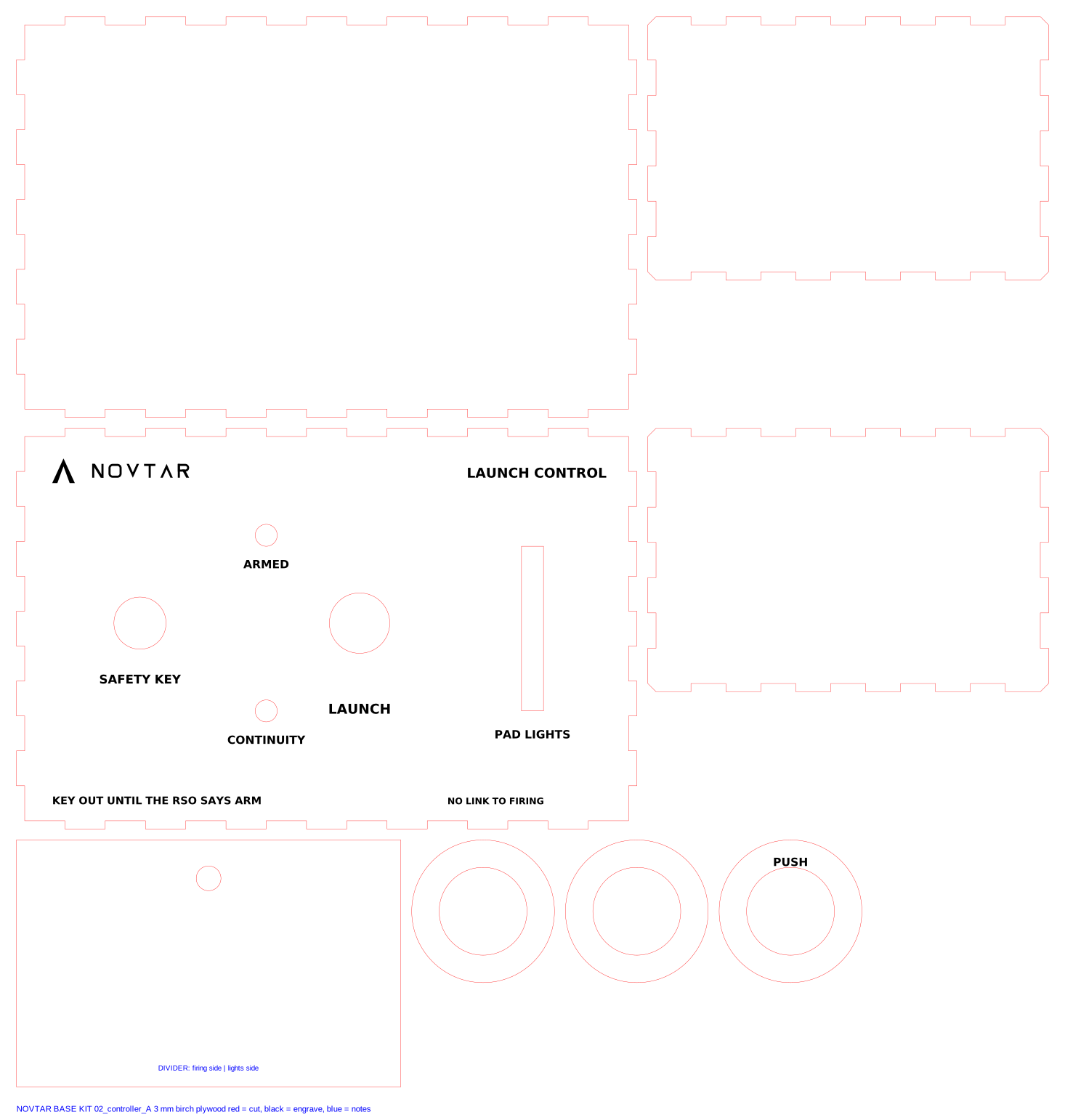
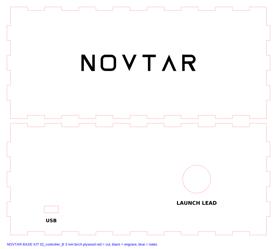
- Box. Finger-jointed, inside 220 x 140 x 90 mm (PLACEHOLDER until your battery is in hand), with a divider: firing side left, lights side right. The guard round the launch button is 3 laser-cut rings.
Your RGB strips, on their own power
We assume your 3-pin RGB strips are WS2812B at 5 V (check the label on the reel). Each leg gets a 240 mm bar, about 14 LEDs at 60 per metre, in an aluminium channel with an opal diffuser, on the outer half of the leg: at least 330 mm from the pivot, below and away from the blast plate.
- Never part of the firing circuit. Two ESP32 boards, each on its own USB power bank. The one in the controller reads only the key's second pole and the button's second contact (dry contacts). It sends the state by radio to the board in the pad lights box under the hub. Neither board has a wire to the battery, the lead or the igniter.
- Display only. The radio message can change colours and nothing else. The RSO's countdown is what launches; the lights only repeat the controller.
- Power. Adafruit: up to 60 mA per LED at full white[5]. The firmware caps the brightness, so the 42 LEDs stay well inside a power bank.
- Wiring. Ground first, then 5 V, then data; a 300 to 500 Ω resistor in each data line and 500 to 1000 µF across the supply; a level shifter, because the board is 3.3 V[6].
- Firmware is in
kit/firmware(PlatformIO):pio run -e pad_lights -t uploadandpio run -e controller_lights -t upload.
Table and antenna mast
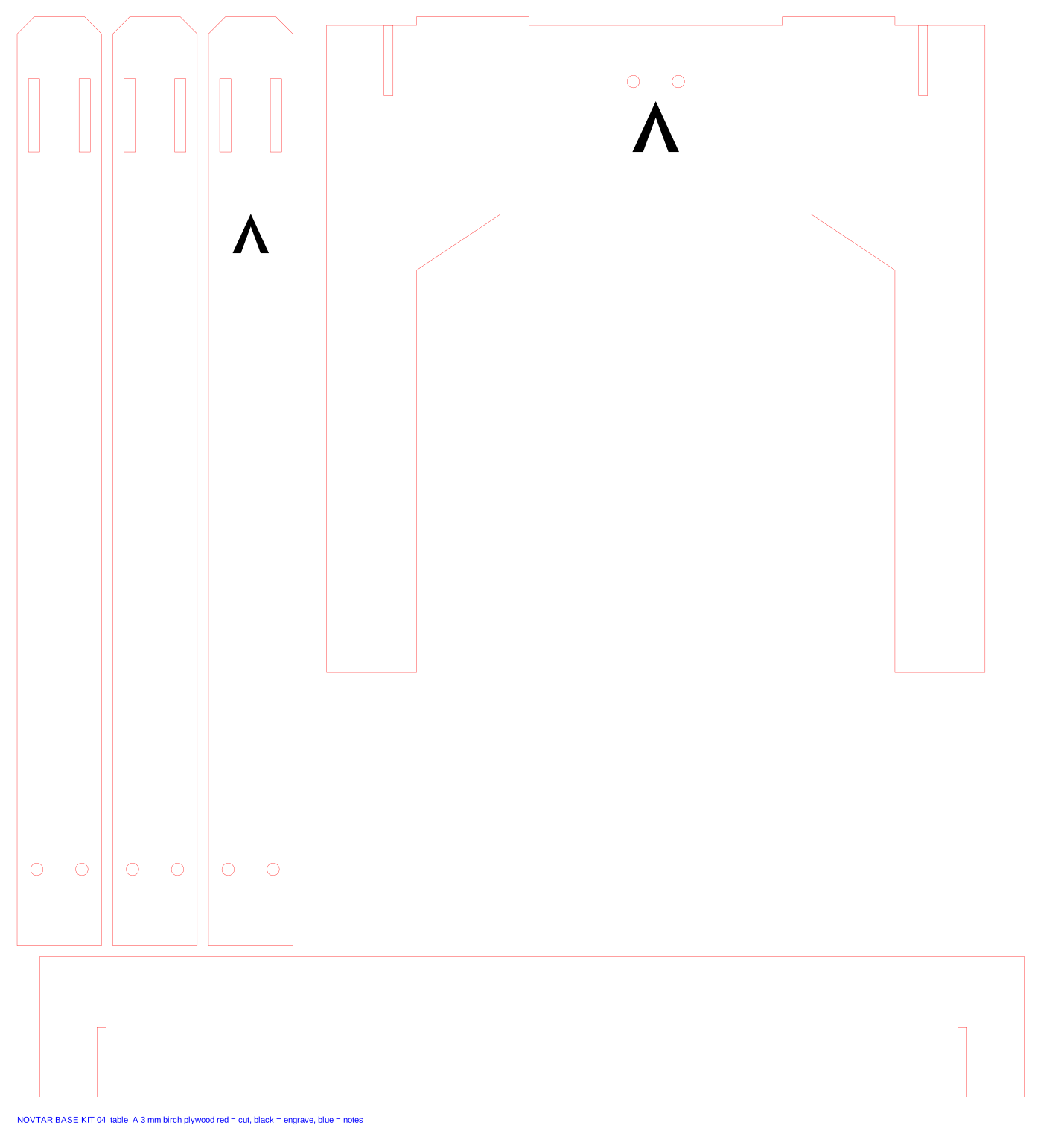
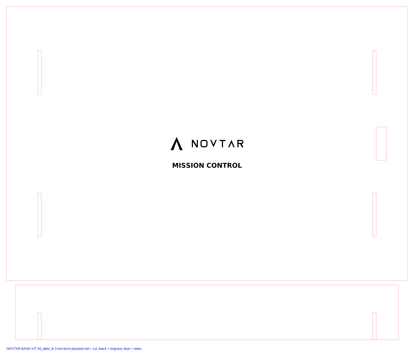
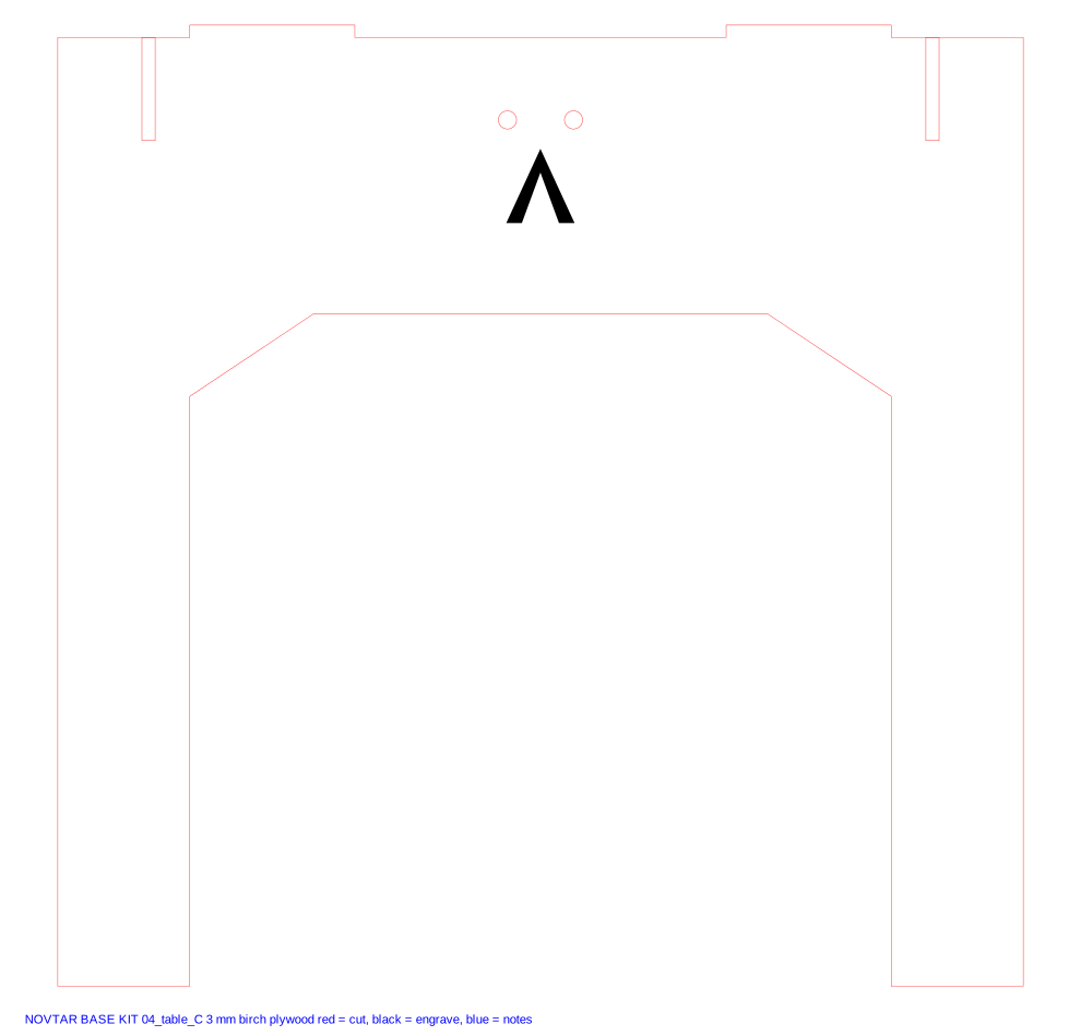
The table slots together with no glue and no tools: a 366 x 250 mm top on two side frames and two ribs, 230 mm high, for the laptop running Mission Control. A 3-layer mast bolts to the outside of a side frame with two wing nuts, clear of the laptop, and lifts the N-1 ground station 280 mm above the top on a hook-and-loop strap, antenna up, for a clearer radio path. It stands with the controller, at least 10 m from the pad.
W-1's launcher packs in the same kit
Rev B of W-1's launcher fixes the clash the renders found: in rev A the bottle's mouth sat on the fitting at the bottom of the pipe while a 165 mm mast stood beside the pipe, so the bottle and its fins would have come down on the mast. Now:
- The bottle seals on the O-ring on a 15 mm compression coupler 180 mm above the hub; the launch tube carries on 200 mm up inside the bottle.
- The post that holds the pipe is 120 mm tall, so its top stays 60 mm below the seal. Above the seal there is only the tube, the cable ties and the collar, all inside the fin can's brace ring.
- The legs push into the hub without glue. For packing they pull out flat, and the head (hub, post and pipework) goes in the bag.
The pressure rules don't change: launch at 40 psi, never above 50 psi, everyone 10 m back. Details, parts and tests: W-1 launcher.
What to buy
No prices: check them when you buy. Plywood: 3 mm birch, 15 sheets.
Launch pad
| Item | Qty | Notes |
|---|---|---|
| 1010 aluminium launch rail (1 inch square) | 2 x 600 mm | Rocketry suppliers sell it cut to length. It has to match N-1's 1010 rail buttons. |
| Joining strip and T-nuts to suit 1010 | 1 set | Joins the two halves in a straight line. Bolts to the rail's back slot. |
| T-nuts and bolts for 1010 (1/4-20 or M6, to suit the T-nuts) | 4 + 1 | 4 hold the rail between the foot cheeks; 1 is the rail stop in the front slot. |
| 20 x 20 x 1.5 mm aluminium square tube | 3 x 620 mm | The legs. Drill each one for the pivot and the lock pin (template in the build book). |
| M6 bolts 50 mm, washers and wing nuts | 6 | 3 leg pivots and 3 leg lock pins. |
| M8 bolt 70 mm, washers and a wing nut | 1 | The rail pivot. |
| M6 bolt 70 mm with a wing nut, on a cord | 1 | The tilt pin. Tied to the yoke so it can't get lost. |
| Swivel levelling feet, M8, with threaded tube inserts for 20 x 20 tube | 3 | Levelling: screw each foot in or out until the bubble is centred. |
| Mild steel sheet 200 x 200 x 2 mm | 1 | The blast plate. Never wood under the motor. Cut the rail notch and drill 4 holes. |
| Steel angle brackets, small | 2 | Hold the blast plate to the foot cheeks. |
| Small bubble level | 1 | Glued to the hub. |
| Tent pegs and cord | 3 + 3 | One from each foot, in wind. |
| 1010 rail buttons for N-1 | 2 | Fitted to N-1 in line with a gap between two fins (N-1 build book). |
Launch controller
| Item | Qty | Notes |
|---|---|---|
| Key switch, 2 pole, key removable only in the off position | 1 | Pole 1 is in the firing circuit. Pole 2 only tells the lights the key is in. |
| Momentary push button, 2 contacts, returns to off when released | 1 | Contact 1 fires. Contact 2 only tells the lights. |
| 12 V sealed lead-acid battery and its charger | 1 | Charged before every launch day. Size it to your igniters; ask the club. |
| Inline blade fuse holder and fuse | 1 | Next to the battery's positive terminal. |
| Red LED, 8 mm panel mount, with its resistor for 12 V | 1 | ARMED: on when the key is in. |
| Green LED, 8 mm panel mount | 1 | CONTINUITY: across the launch button with a 1 kΩ resistor. |
| 1 kΩ resistor, 0.25 W | 1 | The continuity resistor (see the circuit). |
| Panel socket and plug for the lead, a different type from the battery's | 1 | So the lead can never be plugged into the battery. |
| Twin cable, 1.0 mm² or thicker, 15 m | 1 | The launch lead. Wound on the reel. |
| Insulated micro clips | 2 | The igniter end of the lead. |
Pad lights
| Item | Qty | Notes |
|---|---|---|
| Your RGB 3-pin LED strip (WS2812B, 5 V, assumed) | 3 x 240 mm | About 14 LEDs per bar at 60 per metre (check yours). |
| Aluminium LED channel with an opal diffuser | 3 x 240 mm | Protects the strip and spreads the light. Cable-tied to the legs. |
| ESP32 boards (a spare Heltec V3 from N-1's kit works) | 2 | One in the pad lights box, one on the lights side of the controller. |
| USB power banks | 2 | One per board. The lights never use the firing battery. |
| 74AHCT125 level shifter (or similar 3.3 V to 5 V buffer) | 2 | Adafruit: a 3.3 V board needs a level shifter for 5 V pixels. |
| 330 Ω resistor and a 1000 µF 6.3 V (or higher) capacitor | 2 each | Adafruit's NeoPixel best practice: 300 to 500 Ω in the data line, 500 to 1000 µF across the supply. |
| 3-core cable and 3-pin plugs to match your strip | 3 runs | Box to each light bar, cable-tied along the legs. |
| Short strip of 8 LEDs | 1 | The controller's PAD LIGHTS window. |
| Hook-and-loop straps | 4 | Hang the pad lights box under the hub; hold the ground station on the mast. |
Table and crate
| Item | Qty | Notes |
|---|---|---|
| M4 bolts 30 mm and wing nuts | 2 | Bolt the antenna mast to a side frame. |
| Item | Qty | Notes |
|---|---|---|
| Long padded bag, at least the packed length below | 1 | Carries the rail, the folded pad and W-1's launcher. |
| Wood glue | Every finger joint in the crate and the boxes (not the lids). |
Cut list
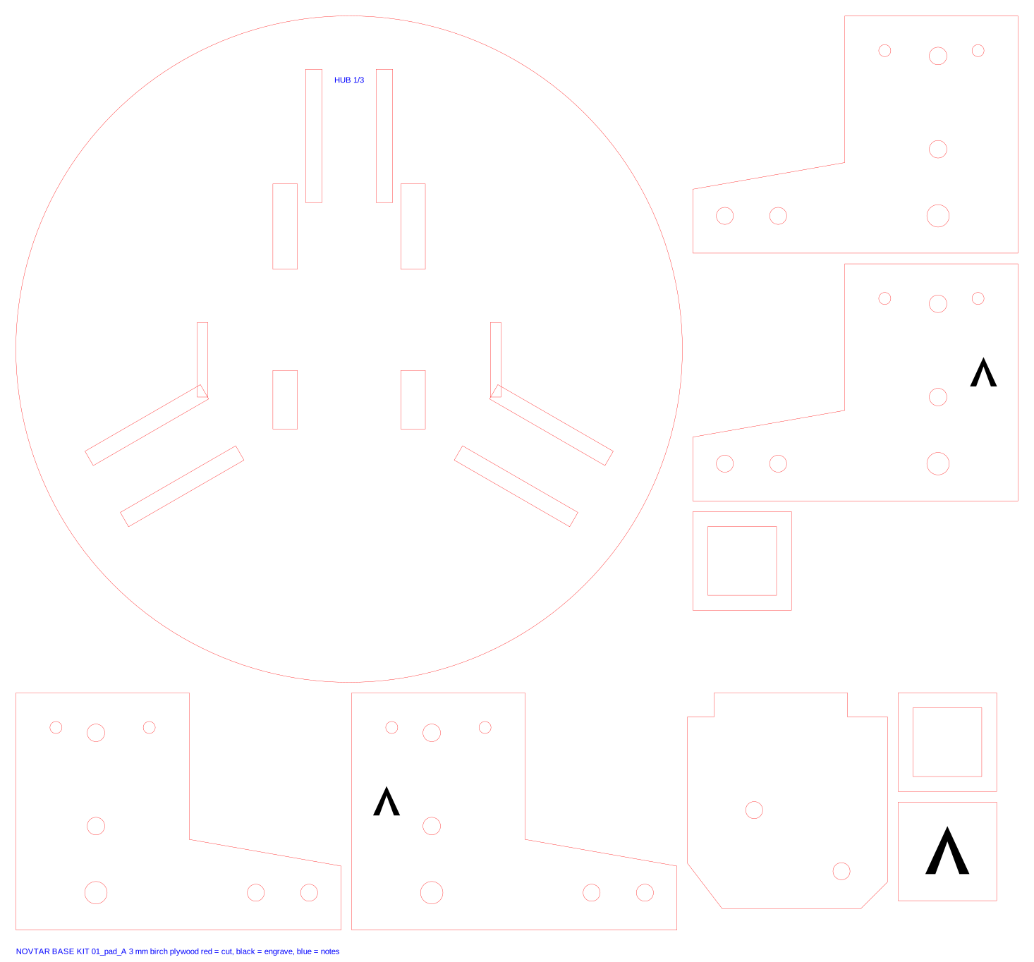
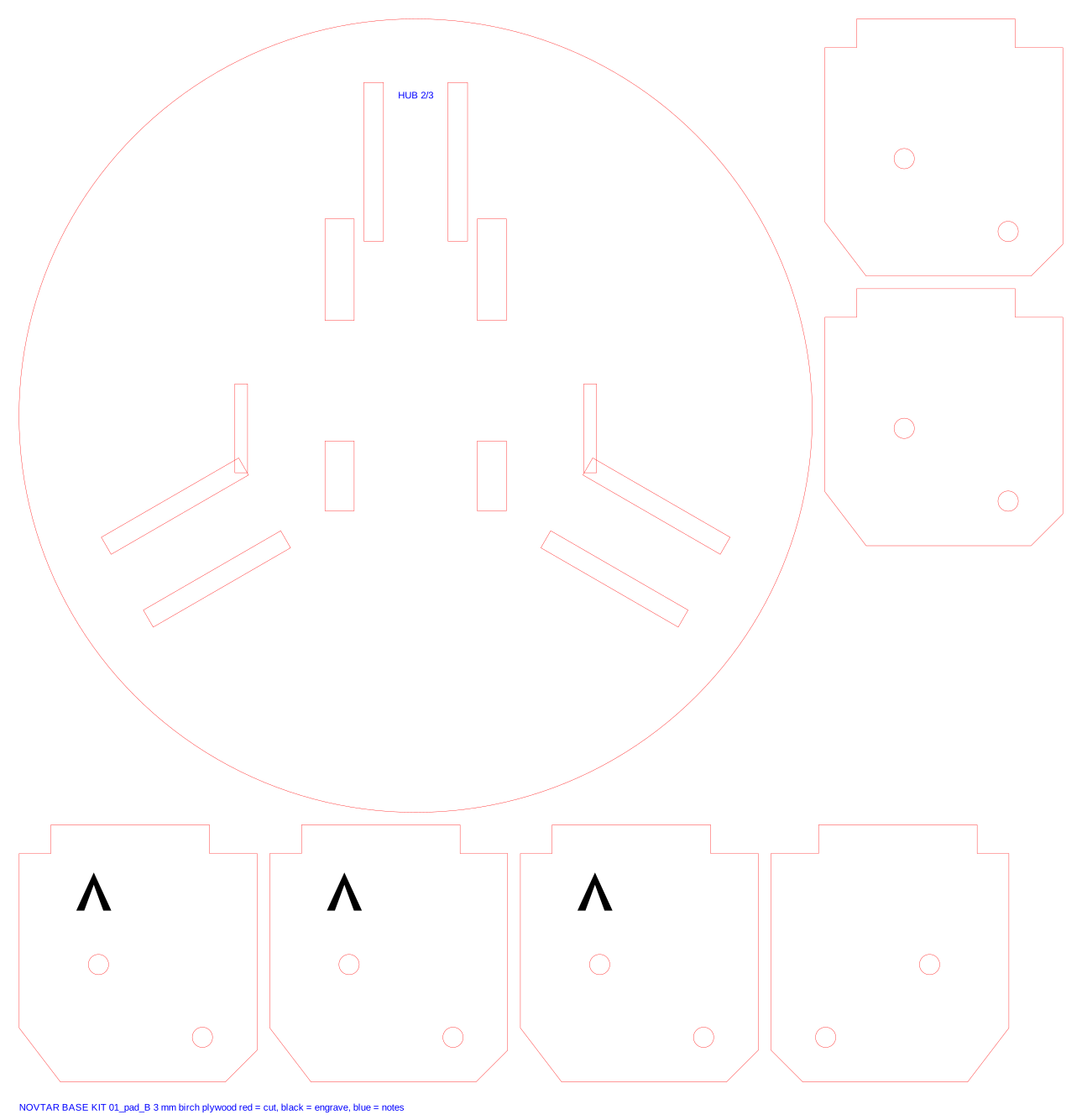
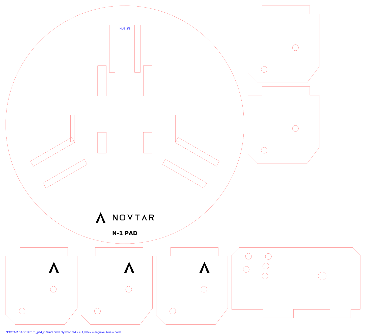
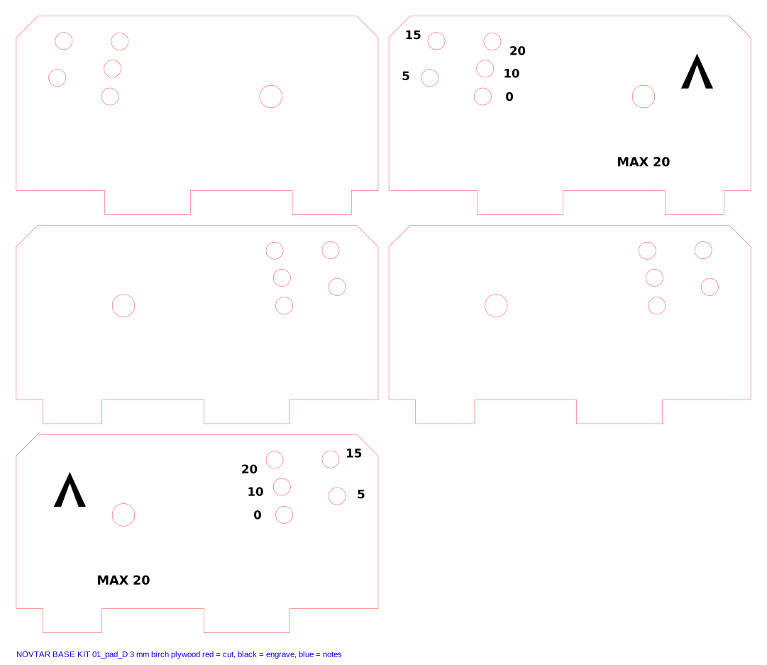
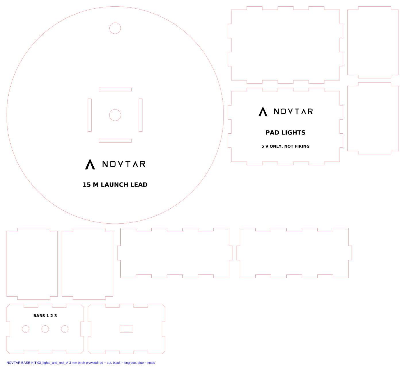
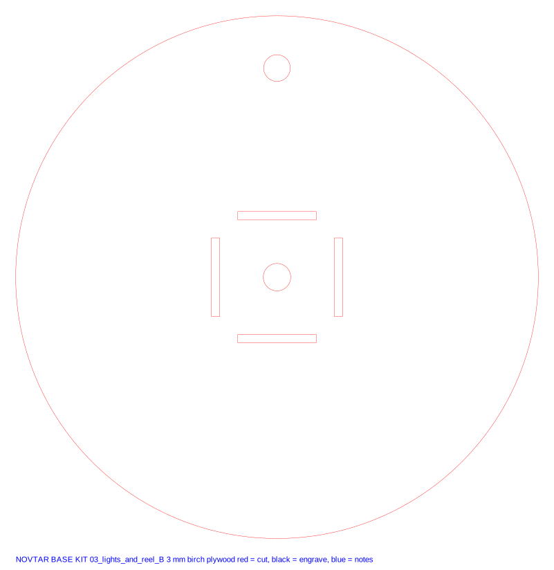
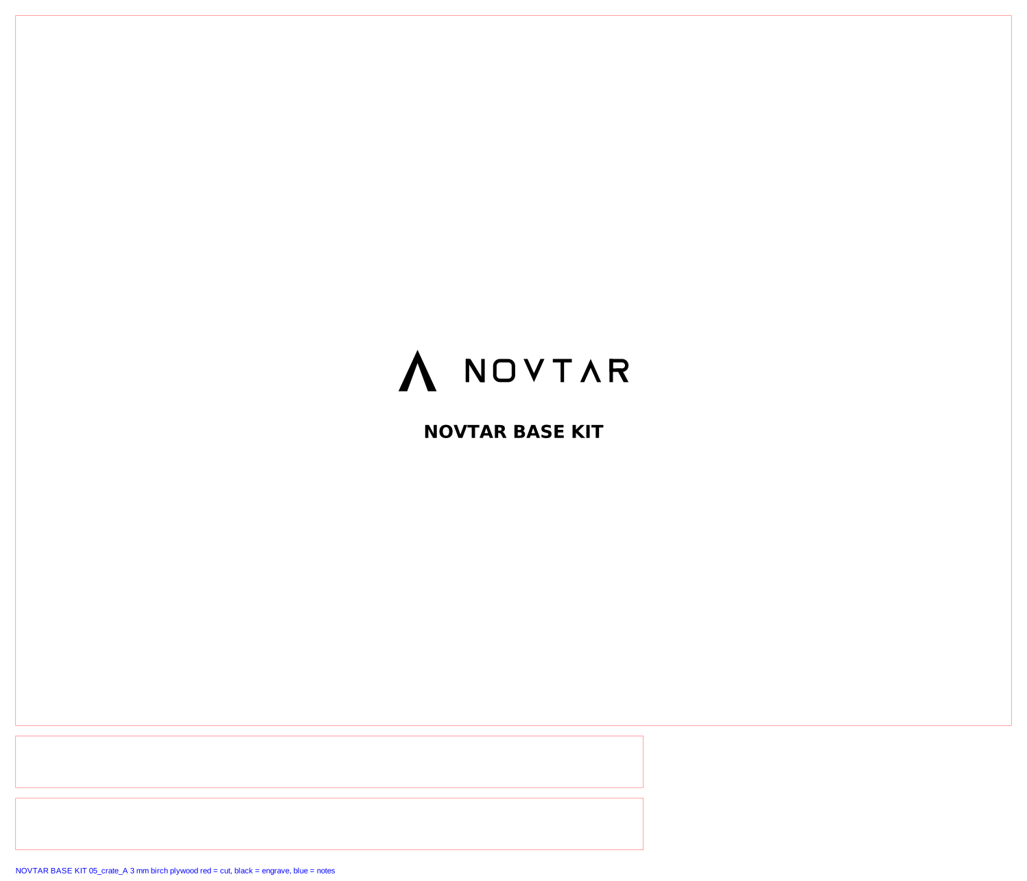
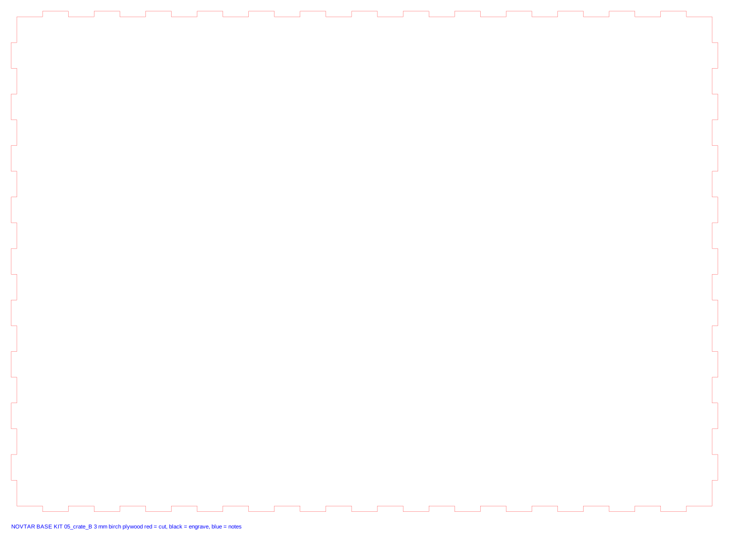
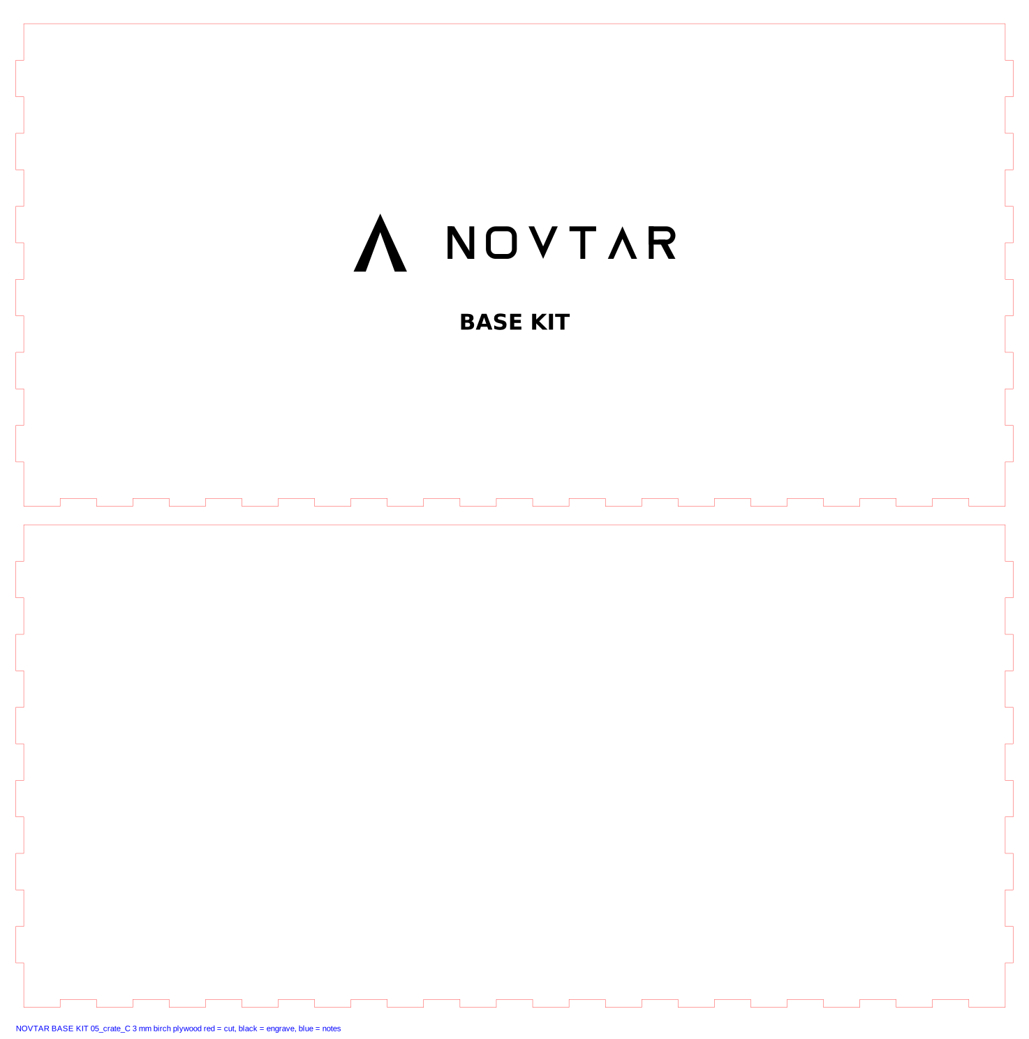
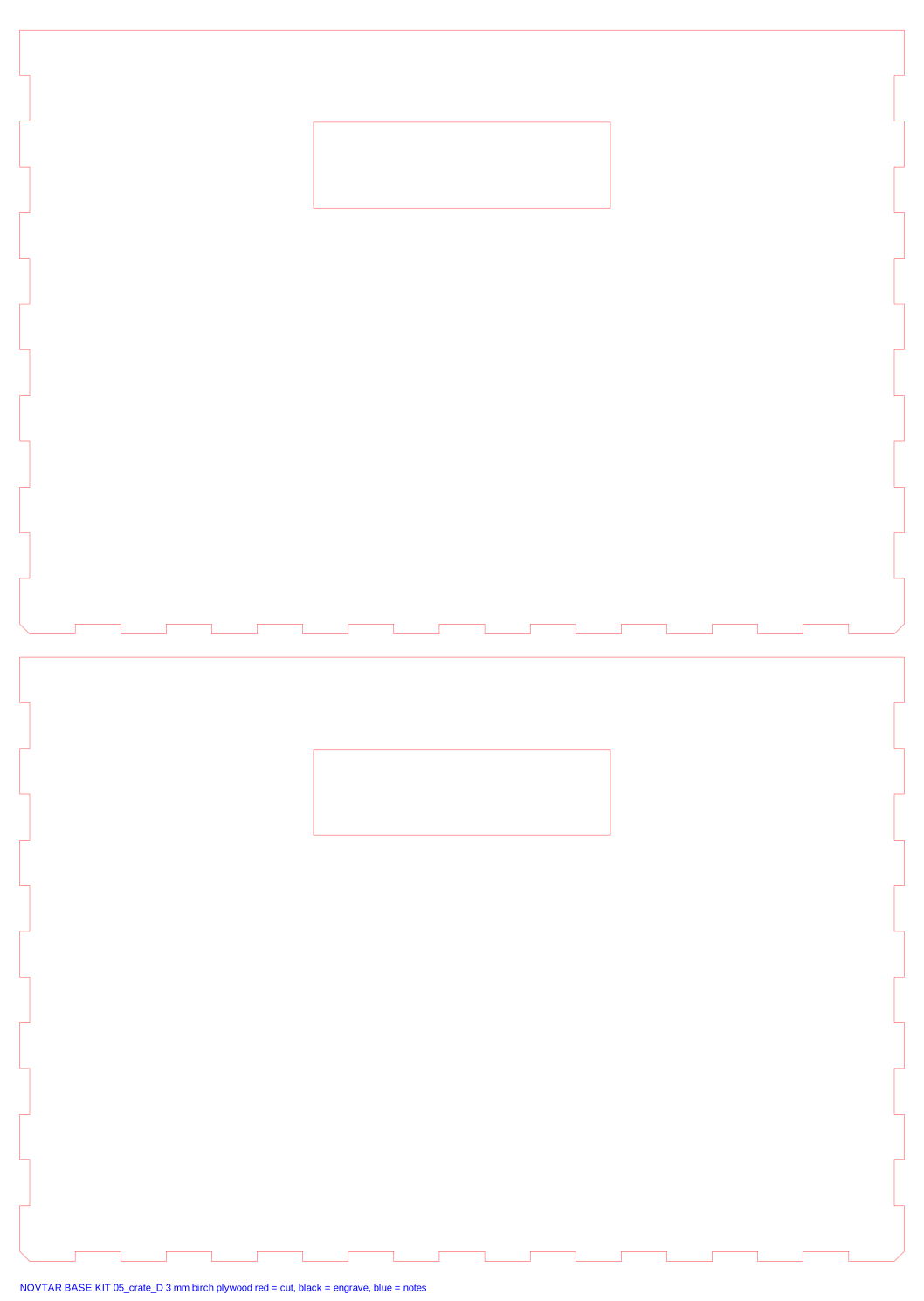
Cut N-1's test card first and copy its kerf and slot play into kit/design.py. Red cuts, black engraves, blue is notes.
Step by step
- Hub. Glue the three hub layers with every slot lined up (push a spare cheek tab through each to align). Glue the bubble level on top.
- Cheeks and yokes. Glue each cheek pair (inner and engraved outer) and each yoke stack, then glue them into the hub slots, square to the hub. Drill nothing: the holes are cut.
- Legs. Use a cheek as a drilling template on each tube: the pivot hole 20 mm from the top end, the lock hole 40 mm below it. Fit the threaded inserts and swivel feet.
- Rail foot and plate. Glue the foot cheek pairs. Bolt them to the bottom of the lower rail half through the T-nuts. Cut the plate's rail notch, drill it, and bolt it on its angles to the cheek tops.
- Rail cap. Glue the 3 cap layers, paint them orange.
- Controller. Glue the box (not the lid) and the divider. Wire the firing side first, exactly as the circuit, then test it (section 11) before adding the lights side.
- Pad lights. Stick each strip in its channel, cable-tie the channels to the legs, run the cables to the lights box under the hub, and flash both boards.
- Reel, table, crate. Glue the reel and the crate. The table and mast are never glued.
Before it goes to a launch
- Key test. Clip a 12 V bulb (the kind for a car's side light) across the lead's clips in place of an igniter. Key out: press the button, the bulb must stay off. Key in: ARMED on. Press: the bulb lights; let go: it goes out.
- Lights don't matter test. Unplug both lights boards' power banks and repeat the key test. It must behave the same.
- Continuity. With the bulb clipped on and the key in, CONTINUITY lights. Unclip one side: it goes out.
- Pad. Set up on flat ground, level it, slide N-1 (no motor) down the rail: it must run freely the whole length. Try every tilt hole; 20° is the last.
- Pad lights. Key out: green. Key in: amber. Press: white, then red for 3 minutes. Switch the controller's lights board off: blue within 2 seconds.
- Pack it. Pack everything in the order below and check it all fits before the first trip.
One crate, one bag
- Bag (at least 769 mm long): the folded pad (250 mm hub, 729 mm long), the two rail halves, the rail cap, W-1's legs and launcher head, tent pegs.
- Crate (outside 384 x 274 x 189 mm): table top flat on the bottom, then the sides, ribs and mast; then the controller (key on your keyring, not in the box), the lights box, the reel, the ground station and the W-1 control panel.
- Fold the pad: take the rail off the yoke (M8 bolt), pull each leg's lock pin and swing the leg down, then put the pins back in their cheeks so they can't get lost.
Checklist
- Battery charged; both power banks charged; key on the keyring.
- Club, RSO and pad agreed. If the club uses its own pad and controller, ours stays packed.
- Pad on a 3 m clear patch, legs pinned, level, pegged. Rail cap on.
- Tilt set by the RSO, 20° at most, away from people.
- Lead run out to the controller, at least 10 m back. Pad lights green.
- N-1 onto the rail. The adult or club fits the igniter at the pad, key out and in a pocket.
- Everyone back. RSO approves, key in (amber), continuity green, countdown from at least five, press, let go.
- Key out straight after. Misfire: key out and wait 3 minutes before anyone goes to the pad.
Sources
Read on 18 November 2026. The club's Range Safety Officer has the final say on everything here.
- [1] UKRA Safety Code (last updated 29 July 2025): 5.3 Launch Rails, 5.4 Launch Controller, 6.3.2 Igniters, 6.4 Launching. https://www.ukra.org.uk/safety-code/
- [2] OpenRocket wiki, Launch Guides Basics. https://wiki.openrocket.info/Launch_Guides_Basics
- [3] UKRA, Safe Launching Distances (part of the Safety Code). https://ukra.org.uk/safety/safety-code/safe-launching-distances/
- [4] Giant Leap Rocketry, airfoil rail buttons (10 series is the 1.0 inch series, for 1010 rail). https://giantleaprocketry.com/products/airfoil-rail-button-pair-10-series
- [5] Adafruit, NeoPixel Überguide: Powering NeoPixels. https://learn.adafruit.com/adafruit-neopixel-uberguide/powering-neopixels
- [6] Adafruit, NeoPixel Überguide: Best Practices. https://learn.adafruit.com/adafruit-neopixel-uberguide/best-practices