N-1 TVC Build book
N-1 TVC, built from plywood and proved on a rig.
A second booster for N-1 that holds it upright during the burn by tilting the motor up to 5 degrees. Every structural part is 3 mm birch plywood off the laser. It is built and tested on a wooden rig with no motor; the firmware starts in shadow mode, where it works out what it would do and moves nothing.
What TVC is here, and what it isn't
Vertical hold only. The gimbal pushes the tail back under the nose so N-1 climbs straight. It has no target and no steering, and none will be added.
No motor on the rig, ever. The rig tests the gimbal, the servos, the signs and the log. A spent motor case stands in for the motor.
Shadow mode first. The firmware only moves the servos on the rig, with the rig plug fitted. Flight mode isn't even in the
firmware unless it's rebuilt on purpose (TVC_FLIGHT_BUILD=1), and then only after three logged rig sessions.
Ask before flying it. Certified motors only, at a UKRA club launch, with an adult or the club handling the motor. Before a flight with the gimbal moving, ask the club's range safety officer and UKRA. We looked for a published UKRA rule on active stabilisation and couldn't find one, so we don't know what they will say; ask them, in writing.
Recovery comes first. A motor's ejection charge would blow straight into the servo bay. So the TVC booster flies on a motor with no ejection charge (if the club confirms one exists in 29 mm that you may fly), and the parachute comes out with the N-1X servo-and-spring module, which has to be proven first. Until then, TVC lives on the rig.
From the design
est. means worked out before building. The torque uses placeholder thrust figures
(100 N peak, 45 N average) until a motor is chosen; put that motor's certified thrust curve into
tvc/design.py and run it again. The servo figures are from distributor copies of the SG90 sheet, which disagree a little[1].
From lean to nozzle
Both pivot axes cross on the motor's centre line, so the thrust passes through the pivot and the servos only fight friction, the motor's own weight swinging, and whatever misalignment the build leaves. Working, with every figure an estimate:
| Pitch | Yaw | |
|---|---|---|
| Lever from the pivot to the pushrod | 17.5 mm | 22.25 mm |
| Pushrod travel at 5° | 1.53 mm | 1.94 mm |
| Servo horn turn at 5° (pushrod 6 mm from the shaft) | 14.7° | 18.9° |
| Turning force needed at the gimbal | 125 N mm | 125 N mm |
| Servo torque needed | 0.44 kgf cm | 0.34 kgf cm |
| Margin against stall (low and high sheet figure) | 2.7 to 4.1 times | 3.5 to 5.2 times |
Gimbal turning force = swinging the motor and cage (30 N mm, 5° in 50 ms) + pin friction (45 N mm, friction 0.3 at peak thrust) + a 0.5 mm thrust line miss (50 N mm). Pushrod force = that / lever; servo torque = force × horn. Pins on plywood at peak thrust: about 4.2 MPa through the brass bushings. Starting gains from a simple model (the rocket as a rod, thrust at the pivot, 2 Hz, 0.7 damping): kp 0.534, kd 0.0594 s; in a simulation with the limit, a servo lag and a 100 Hz loop it settles a 3° lean in about 0.16 s using 1.05° of gimbal. That model is only a start: real gains need real thrust.
What can't be wood
Laser-cut birch plywood, all 3 mm from the S9 Pro: the cage cheeks, cage rings, pitch horn and thrust cap; the middle frame's rings and plates (with the yaw horn ear); the fixed plates and washers; bulkheads B1 to B4; both servo mounts; the electronics sled; the fins; the gluing jigs; and the whole test rig (uprights, base, swing stop, both frames). That's every part where wood can carry the load. These can't be, and here's why:
| Part | What it is | Why not wood |
|---|---|---|
| Pivot pins | 3 x 8 mm and 3 x 10 mm hardened steel dowel pins | They carry the motor's whole thrust in shear. A wooden pin would crush or snap. |
| Bushings | 4 mm brass tube, about 3.1 mm bore, cut to the plywood's thickness | Plywood wears into an oval round a turning pin; brass keeps the pivot tight. |
| Cage tube | 29 mm motor mount tube (kraft paper), the same tube N-1 uses | It wraps the motor case; a plywood stack would be heavier for the same job. |
| Pushrods | 1.2 mm steel wire with a Z-bend at each end | Thin, stiff and doesn't stretch. Wood can't be bent into a Z. |
| Servos | Two 9 g micro servos, metal gears recommended | They are the motors that move the gimbal. |
| Servo horns | The nylon horns that come with the servos | They grip the servo's splined shaft. Plywood can't hold a spline, and a 3 mm plywood arm won't fit the 2 mm between the servo and its pushrod. The horns they push on, on the cage and the frame, are plywood. |
| Electronics and power | A second N-1 flight computer board, an MPU6050, a small 2S LiPo and a 5 V regulator (BEC) for the servos | Bought parts, as on N-1. |
| Glue | Epoxy for every joint that carries thrust | Wood glue isn't strong enough at the pins and the thrust cap. |
| Heat | Nothing: no wood sits behind the nozzle, and the nozzle sticks out 8 mm past the tube | The motor case gets hot after the burn. N-1 already has kraft and plywood round its motor; check the cage for scorching after every test. |
What to buy
No prices: buy from the shops you already use for N-1.
| Item | How many | Notes |
|---|---|---|
| 3 mm birch plywood | 2 sheets for the gimbal, servo bay and fins; 4 more for the rig (400 x 410 mm bed) | |
| 29 mm motor mount tube (kraft) | at least 130 mm (the cage tube is 127 mm) | Same tube as N-1 |
| Booster tube | 480 mm, same as N-1's | Fins slot through the wall only |
| Hardened steel dowel pins | 2 of 3 x 8 mm (pitch), 2 of 3 x 10 mm (yaw) | |
| Brass tube, 4 mm outside, about 3.1 mm bore | about 30 mm | Cut into 3 mm bushings |
| Steel wire, 1.2 mm | about 300 mm | Pushrods with Z-bends |
| Micro servos, 9 g, metal gear | 2 | Body about 23 x 12.2 x 29 mm[1] |
| Heltec WiFi LoRa 32 V3 and an MPU6050 board | 1 each | The same parts as N-1's flight computer |
| 2S LiPo, about 300 mAh, and a 5 V regulator (BEC) | 1 each | Pick a regulator that can supply both servos at stall; one source puts a single SG90 at about 550 mA[2] |
| Servo power board: perfboard and 2.54 mm pin headers | a small piece, two 3-pin headers | Takes 5 V to both servos and their signals to the board |
| Slide switch, USB-C panel socket and short USB-C extension (right-angle plug) | 1 each | Mounted on the plywood service port plate |
| JST-XH 2-pin socket and plug | 1 pair | The rig plug: its two pins joined, fitted only on the rig, with a red tag |
| Wire: 22, 24 and 26 AWG silicone, in several colours | a metre of each | Lengths in the wiring table |
| Cable ties, 2.5 mm wide, and heat-shrink | a small pack each | |
| Epoxy (30 minute) | small pack | Every joint that takes thrust |
| Rig: M5 x 20 bolts, nylon-insert nuts, washers | 4 bolts, 4 nuts, 8 washers | |
| Rig: a spent 29 mm motor case | 1 | Stands in for the motor. Never a live motor |
Eight sheets, in this order
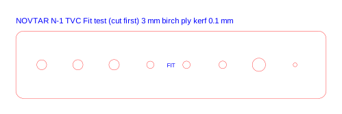
bush_od and pin_fit in design.py.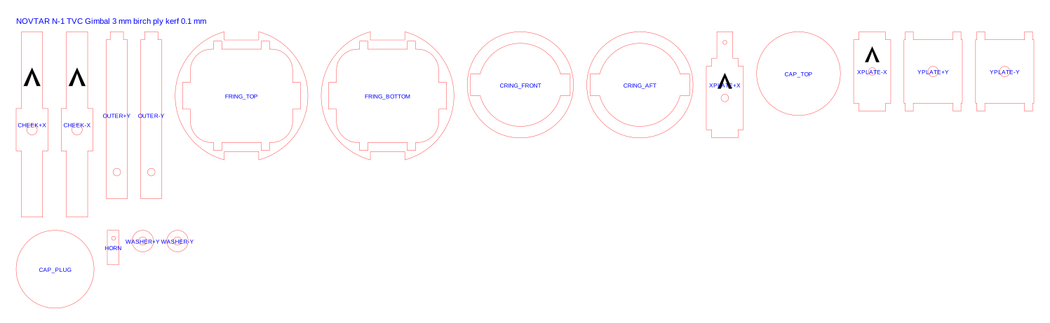
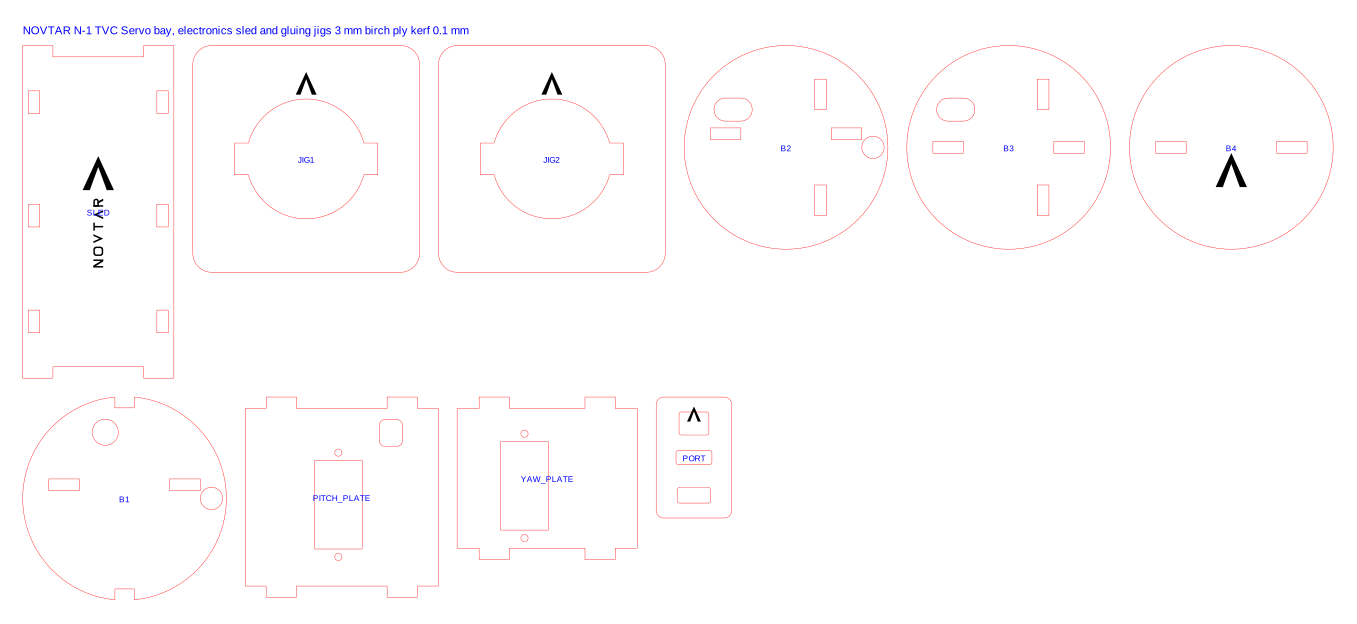
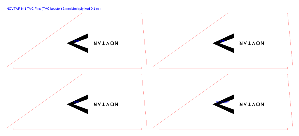
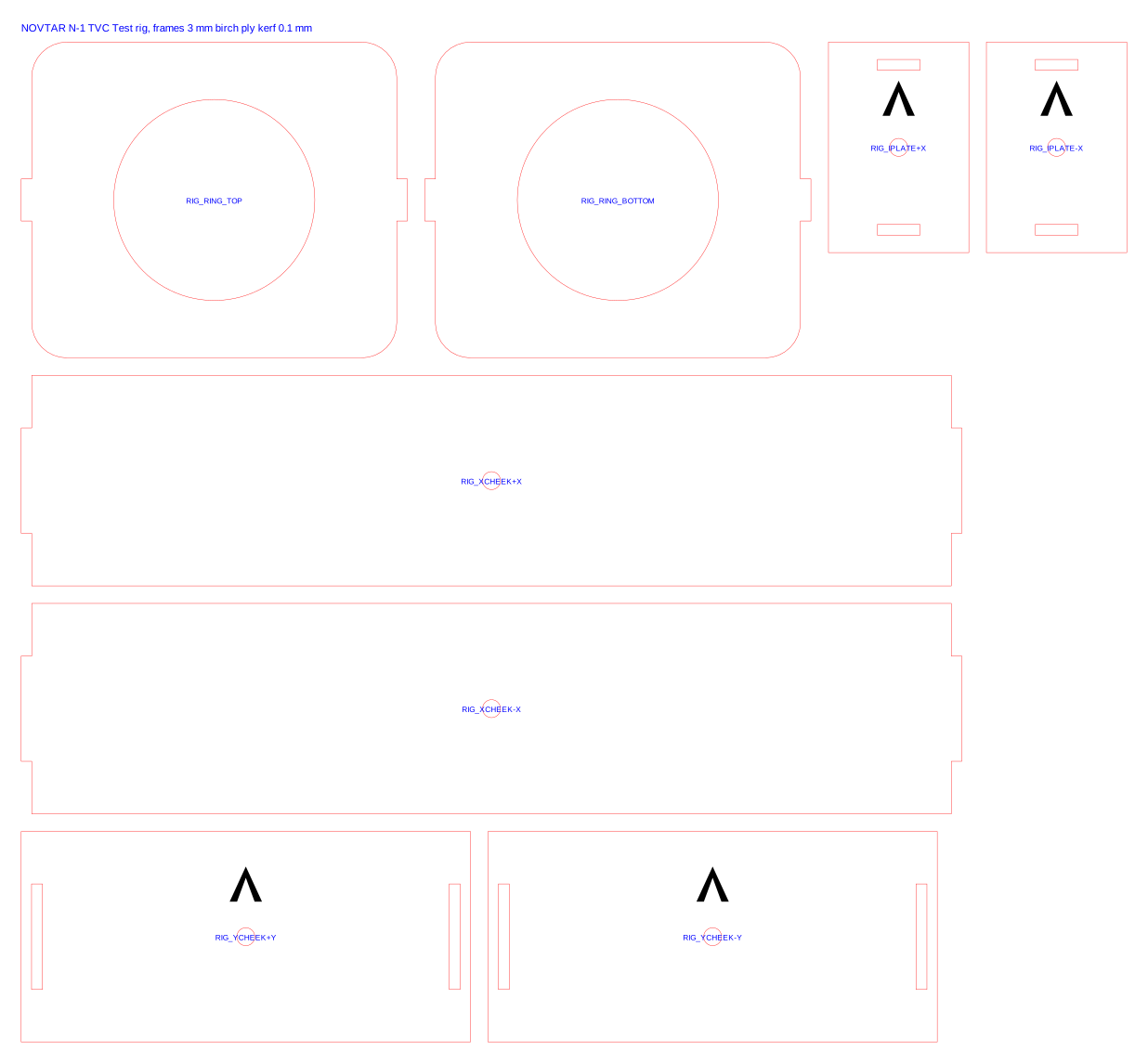
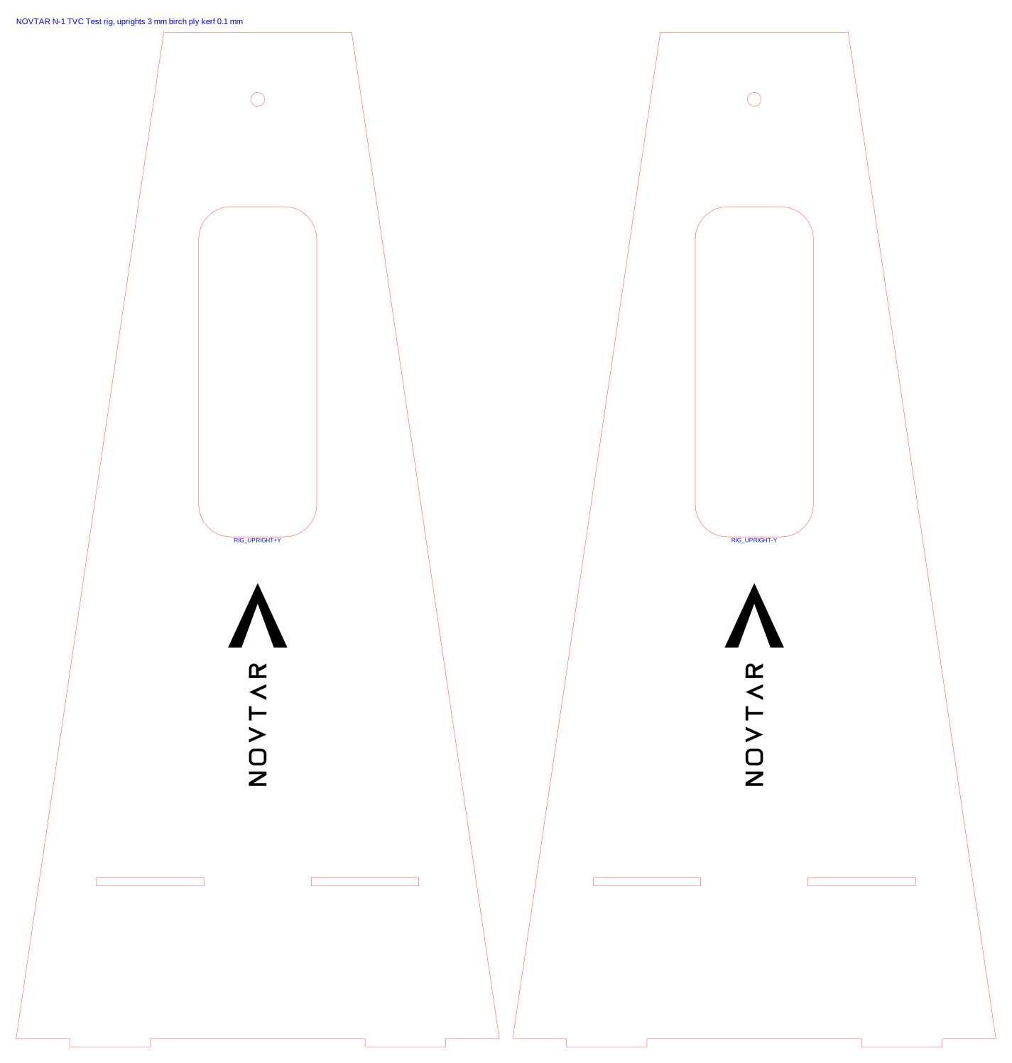
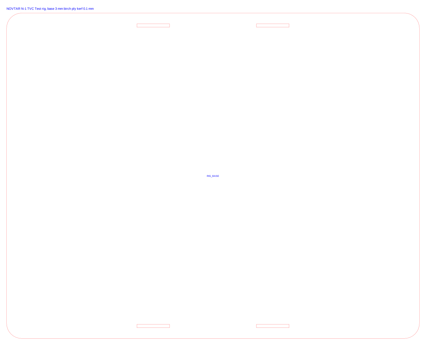
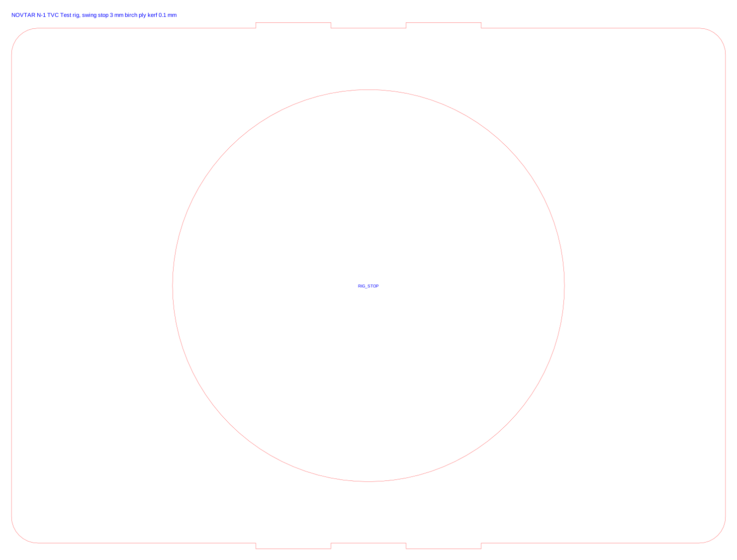
Same laser settings as N-1's plywood (see its build book). Red cuts, black engraves, blue is notes.
Step by step, as it goes together
Cut the fit test first and pick the hole sizes that suit your pins, bushings and bolts. In each picture the parts that step adds are in colour and the earlier ones are grey. The 3D model has the same steps on a slider.
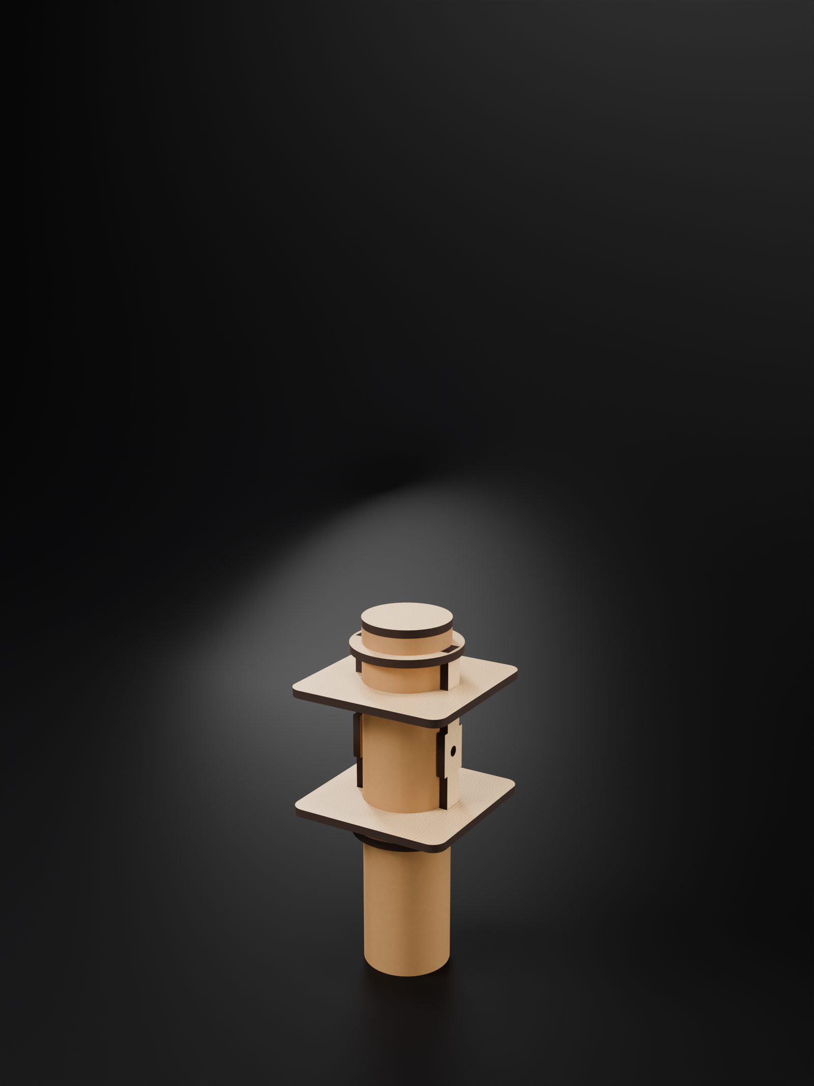
- Glue the cage. Slide the two gluing jigs onto the cage tube and drop the cheeks into their slots, so they sit flat, exactly opposite and with the pivot holes level. Glue the front and aft cage rings over the cheeks, the pitch horn between them, and the thrust cap plug and top on the front end. Epoxy with fillets; keep the inside of the tube clean so the motor slides in.
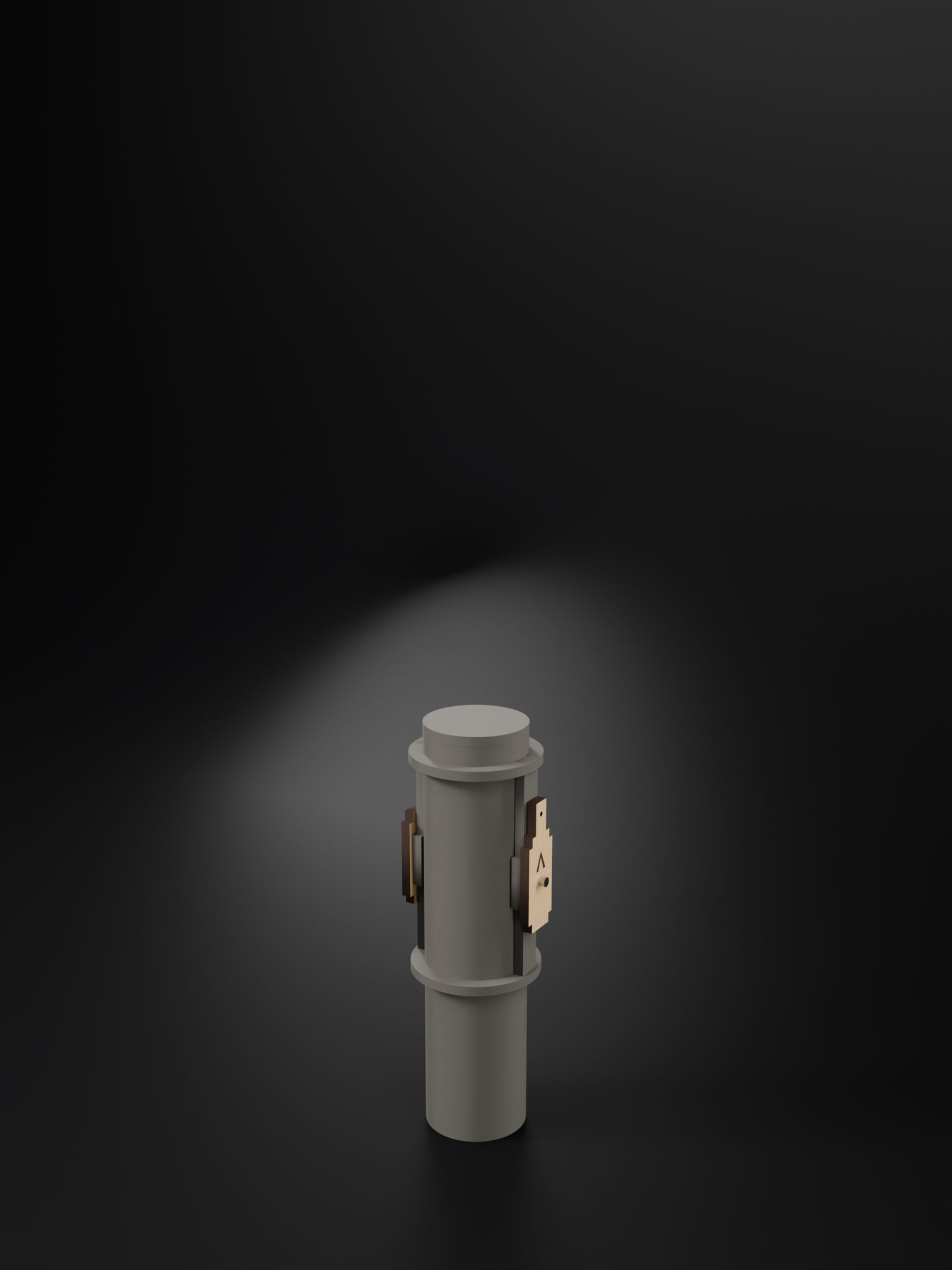
- Fit the pins and bushings. Press the brass bushings into the two cheeks and trim them flush. Glue the 3 × 8 mm pitch pins into the two frame x plates only, then hook the plates onto the cage so the pins run in the bushings. The cage must swing freely.
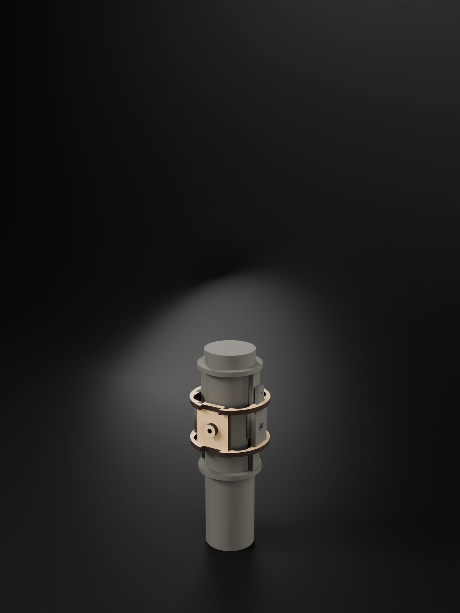
- Fit the frame. Press the bushings into the yaw plates. Build the frame round the cage: the two frame rings on the x plates' tabs, the yaw plates between them, the plywood washers on the outside. Check the cage still swings 5° each way.
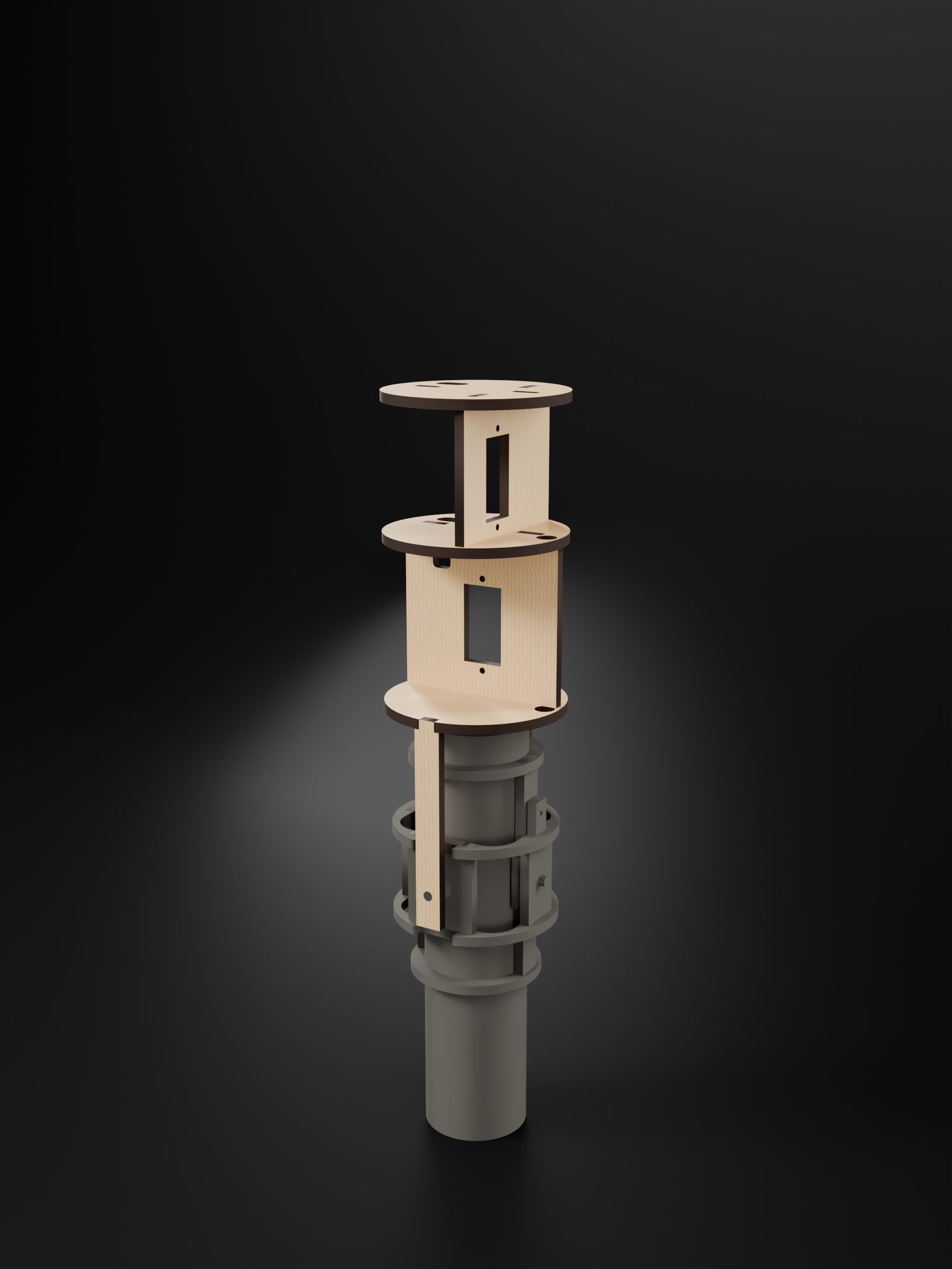
- Mount the plates. Fit the yaw pins through the fixed plates and the washers into the yaw bushings, gluing the pins into the fixed plates only. Glue the fixed plates' tabs into B1, then the pitch servo plate between B1 and B2 and the yaw plate between B2 and B3. Check the frame swings 5° each way, then in a circle.
- Fit the servos and pushrods. Screw both servos to their plates with the screws that came with them. Power them on the bench and centre them (
centre), then fit the horns pointing as drawn. Bend a Z in each wire, hook it through the cage's pitch horn or the frame's ear, mark the length at the servo horn, bend the top Z into the horn.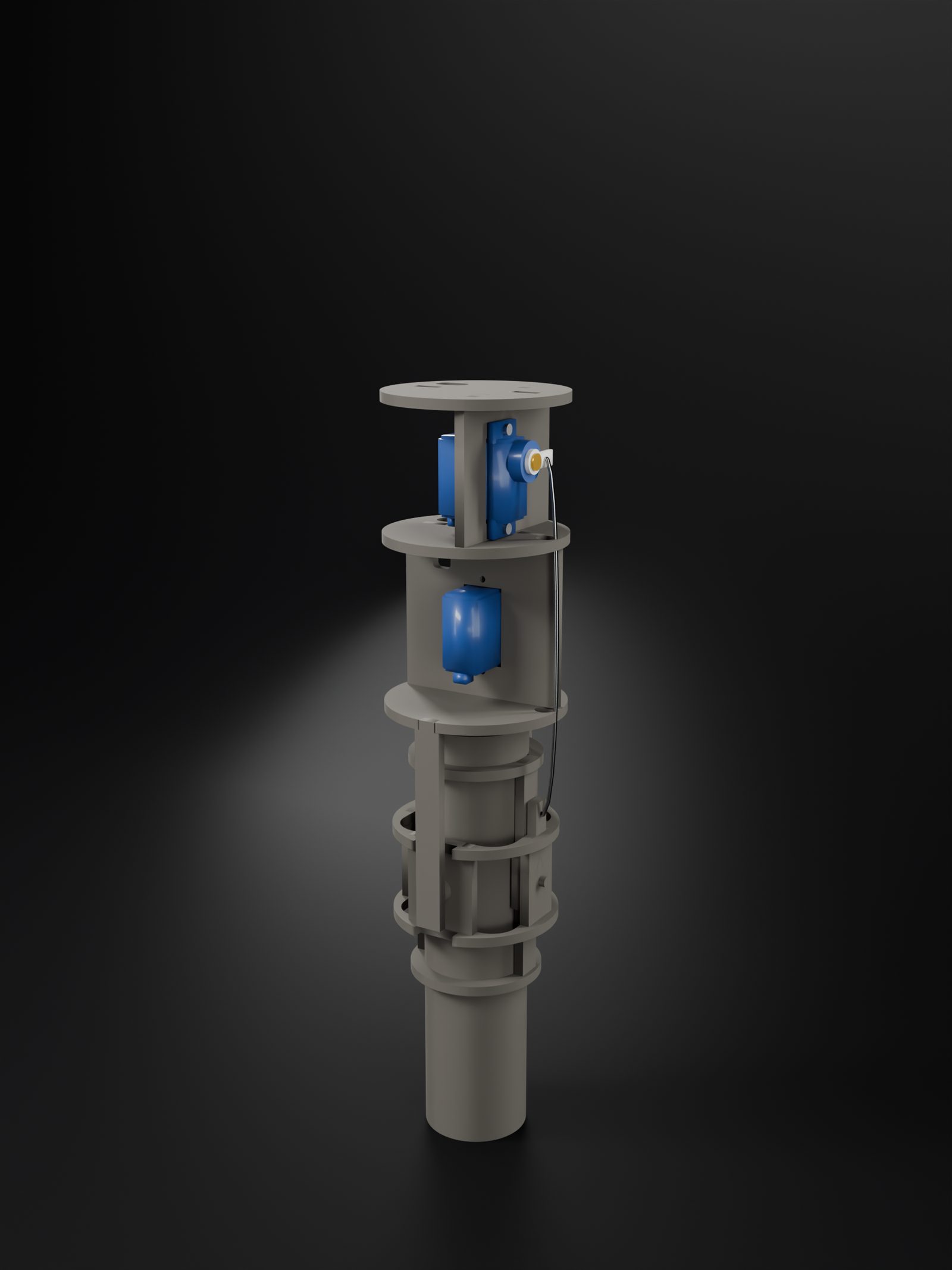
- Run the wiring. Glue the sled between B3 and B4 and the service port plate in place. Board and MPU6050 on the sled's front, LiPo and regulator on the back, held by ties through the slots. Run every cable as in the wiring table: the servo leads up the side, through the slot in B2 and B3 to the servo board; the battery round the sled's edge to the switch; the regulator to the servo board and the board. Tie each run.
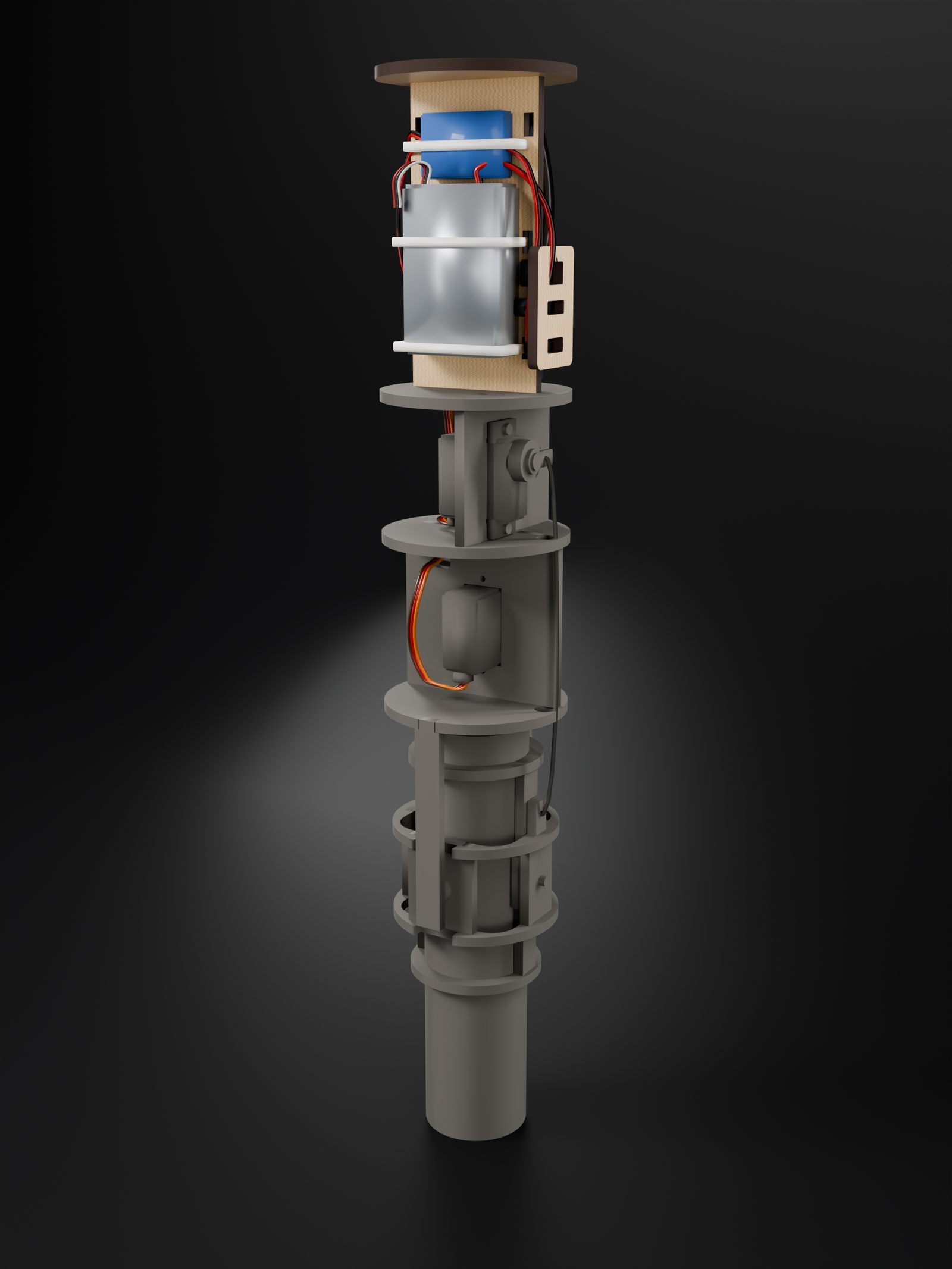
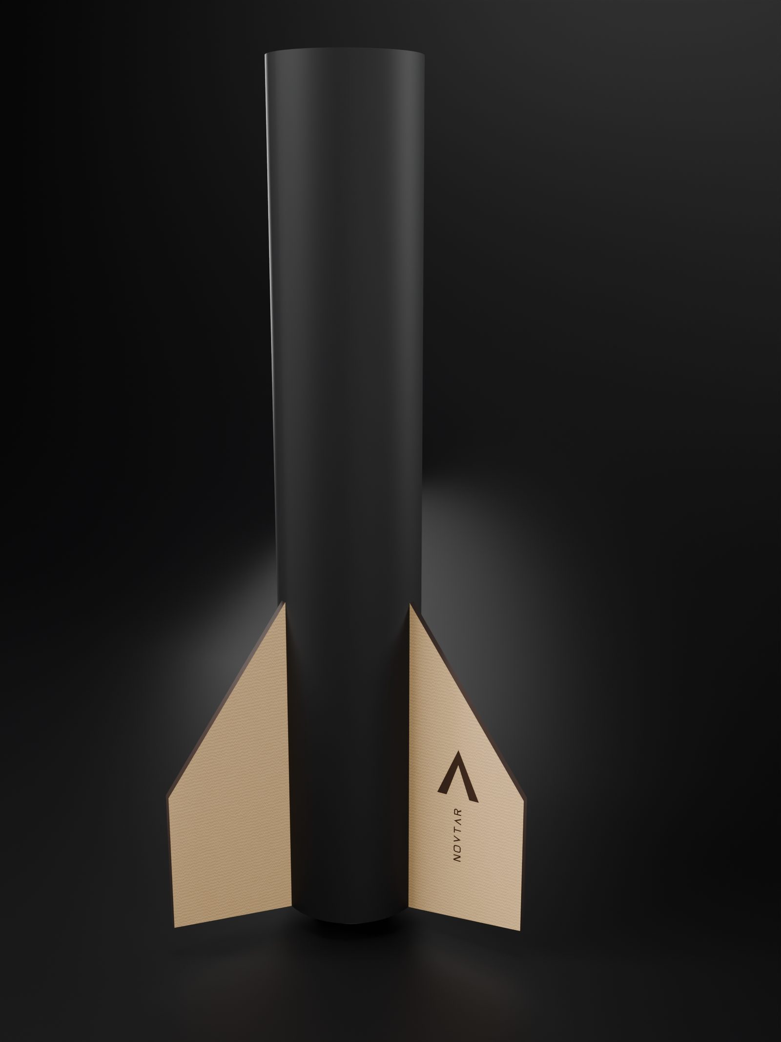
- Close up the booster. Cut the service port window in the booster tube (about 20 × 34 mm, estimate) and slide the stack in from the aft end until the cage tube sits 8 mm proud and the port lines up. Glue B1 to B4 to the wall. Glue the fins through their slots with fillets inside the slot and outside.
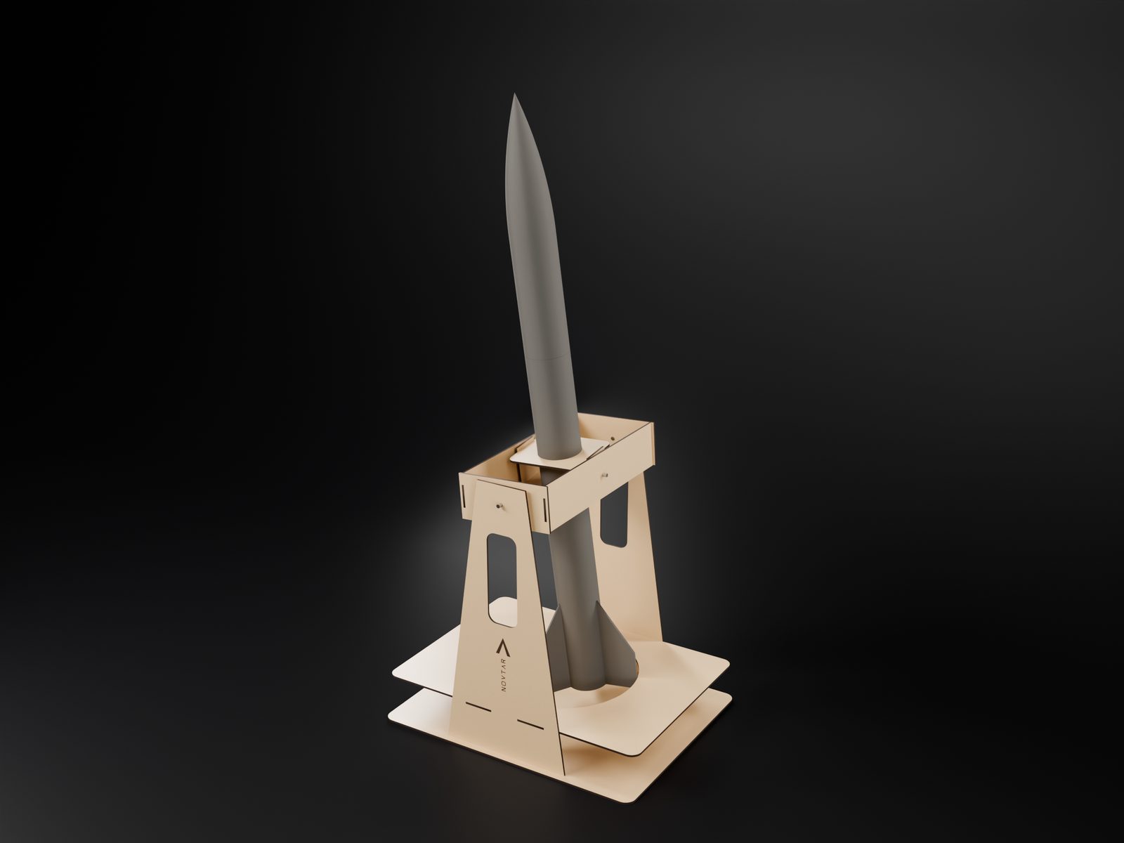
- Assemble the rig. Uprights into the base, the swing stop between them, the outer frame on the Y bolts and the inner frame on the X bolts, nylon-insert nuts snug but free. Slide the finished rocket, with a spent case in the cage, into the clamp rings until it balances, and fit the rig plug.
Every cable, accounted for
One battery runs everything: the 2S LiPo through the slide switch to a 5 V regulator, which feeds the servos (through the servo power board) and the board. Lengths are measured along each cable's route in the 3D model, plus 30 mm to work with (estimates).
| From | To | Wire | Length (est.) |
|---|---|---|---|
| Pitch servo | Servo power board | Servo's own 3-core lead (brown, red, orange) | 155 mm |
| Yaw servo | Servo power board | Servo's own 3-core lead (brown, red, orange) | 99 mm |
| Servo power board | Board GPIO 5, GPIO 6, GND | 3 × 26 AWG (yellow, green, black) | 46 mm |
| MPU6050 | Board 3.3 V, GND, GPIO 17 (SDA), GPIO 18 (SCL) | 4 × 26 AWG (red, black, blue, yellow) | 42 mm |
| 2S LiPo | Power switch | The pack's own lead (red, black) | 90 mm |
| Power switch | 5 V regulator input | 2 × 22 AWG (red, black) | 88 mm |
| 5 V regulator output | Servo power board | 2 × 22 AWG (red, black) | 91 mm |
| 5 V regulator output | Board 5 V and GND | 2 × 24 AWG (red, black) | 61 mm |
| 2S LiPo | Folded and tied (charger only) | The pack's own balance lead | 51 mm |
| Rig plug socket | Board GPIO 7 and GND | 2 × 26 AWG (yellow, black) | 54 mm |
| Board USB-C | Service port socket | USB-C extension lead | 99 mm |
Cables cross the bulkheads only through the slot in B2 and B3 (10 × 6 mm, wide enough for a servo plug) and the pitch servo plate's notch; the design checks that every routed cable stays inside the tube with 2.42 mm to spare. Servo lead colours are the SG90 sheet's: brown ground, red +5 V, orange signal[1].
Drawn to these sizes
| Part | Size | From |
|---|---|---|
| SG90-class servo | Case 23 × 12.2 × 22.7 mm, 32.2 mm across the ears, 9 g, lead brown, red, orange | SG90 sheet (distributor copy)[1] |
| Servo output spline | About 4.8 mm across (20 or 21 teeth: sellers differ) | Kpower's micro-servo table[3] |
| Ear thickness, boss, horn, lead exit | 2.5 mm ears, 11.6 mm boss, horn 4.5 mm above the case | Estimates: measure yours |
| Heltec WiFi LoRa 32 V3 | 50.2 × 25.5 × 10.2 mm, USB-C | Heltec product page[4]; USB-C position estimated |
| GY-521 (MPU6050) | About 21 × 16 mm, two 3 mm holes | Seller listings, which differ by about 1 mm[5] |
| 2S 300 mAh LiPo, 5 V regulator, servo board, switch, sockets | 45 × 30 × 13, 25 × 17 × 7, 18 × 14 mm and so on | Estimates for typical parts: change them in tvc/parts.py once yours arrive |
Proving it with no motor
The rig is a free two-axis frame on a base: N-1 hangs on its balance point and can lean about 15° any way before the swing stop catches it. Pivot 353 mm up, M5 bolts in plywood, all from the laser.
- Balance N-1 in it: slide the assembled rocket (with the spent motor case in the cage) through the clamp rings until it hangs level; its balance point is then on the pivot, about 320 mm from the tail (estimate). A wrap of tape where the rings grip.
- Shadow first: power up without the rig plug.
statusmust say SHADOW and servos off. Tip the rocket by hand and watch the lean and the gimbal it would ask for. Nothing moves. - Rig mode: fit the rig plug, type
rig on, hands clear.centre, then settrim pandtrim yuntil the motor case sits dead centre in the tube. - Limits:
sweepruns both axes to 5° and round a circle. Nothing may touch the tube or the fixed plates; nothing may bind or flex. If it does, stop and find out why. - Signs, the most important test: lean the rocket so the nose goes towards the +x side of the rig. The nozzle must swing towards the −x side, the opposite side to the lean (that pushes the tail back under the nose). If it swings the same way, type
flip p(orflip yfor the other axis) and test again. Do both axes, both ways. - Push tests: nudge the rocket and let it swing. The gimbal should follow the lean and its speed smoothly, without buzzing. Download the log (
ls,dump) and look at it in the report tool. - Three sessions: repeat on three different days. Each
rig onis counted. That's the minimum before flight mode can even be switched on. - What the rig can't tell you: with no thrust, nothing turns the rocket, so the rig checks direction, limits, timing and logs, not the gains. The first test with real thrust would be on a proper static test stand, run by the club or an adult; we haven't designed that stand.
Three modes, shadow by default
The code is in tvc/firmware (PlatformIO, the same board and IMU library as N-1). The gimbal sizes and gains come from
tvc_config.h, which design.py writes, so they can't drift. Nothing in it fires, releases or deploys anything.
| Mode | How you get there | What it does |
|---|---|---|
| SHADOW | Always at power-up | Works everything out and logs it. Never sends a servo signal. |
| RIG | Rig plug fitted and rig on | Moves the servos. Pull the plug and it drops to SHADOW at once. Launch detection is off. |
| FLIGHT | Only in a firmware built with TVC_FLIGHT_BUILD=1, then flight enable after 3 rig sessions, plug out | Moves the gimbal during the burn only (at most 3 s), centres it after, and centres and stops for good past 15° of lean. |
Not tested on hardware yet. Commands over USB at 115200: status, rig on, rig off,
centre, sweep, trim p|y <us>, flip p|y, ls, dump <n>, rm.
Tight, and where
A two-axis gimbal round a 29 mm motor inside a 54 mm tube is tight. The design checks every gimbal part at 5° all the way round:
the closest anything gets to the tube wall is 0.75 mm (frame ring, top), and the closest a moving
part gets to a fixed one is 1.39 mm. Plywood varies and tubes aren't perfectly round, so measure yours and run
design.py again before cutting. The fins lose their through-the-wall tabs to the gimbal and are held by the slot and fillets
only, which is weaker than N-1's. The added 114 g at the tail brings the stability down from
1.87 to 1.37 calibres (estimate), still above 1.
Sources
Read on 18 November 2026. Everything else on this page is worked out in tvc/design.py.
- [1] SG90 9 g micro servo data (distributor copy of the TowerPro sheet): 1.8 kgf cm at 4.8 V, 23 x 12.2 x 29 mm, 9 g. https://bit.nkust.edu.tw/~csshieh/teach/111A/mc/datasheet/SG90.pdf
- [2] Circuit.Rocks, SG90 9g Servo (notes on stall current and supply). https://docs.circuit.rocks/motors/sg90-servo/
- [3] Kpower, micro servo dimensions (notes that SG90s from different makers differ in ear position and thickness). https://www.kpower.com/insight_servo/2399.html
- [4] Heltec Automation, WiFi LoRa 32 product page (50.2 × 25.5 × 10.2 mm). https://heltec.org/project/wifi-lora-32/
- [5] Flux Workshop, GY-521 MPU-6050 module listing. https://fluxworkshop.com/collections/abd-sensors/products/bdaa100044-gy-521-mpu-6050